8
Please note: The dust filtration systems of RSDE1 and RSDE2 consist of a cartridge filter and outer disposable
paper filter bag to provide 0.5 micron filtration.
The DX4000 and DX5000 feature additional cloth filters for improved filtration and extended filter life.
PLEASE NOTE: The clamp which fixes the hood assembly to the drum body of your machine is fitted to
protect the unit during transit and should not be used once the extractor is installed.
1. Attach one end of the flexible hose to the machine inlet and secure with a Jubilee clip or easy fit cuff
(Not supplied with RSDE1).
2. Place the cartridge filter with open end uppermost inside a paper filter-bag and fold the top edges of the
paper bag down inside the cartridge, making sure not to fold the edges any more than 50mm inside the
cartridge filter. Push this on to the motor body; making sure that it is securely positioned.
3. Position the hood unit on the machine body.
4. After carefully positioning the end of the flexible hose for maximum effect, connect to power outlet.
Your dust extractor is now ready for use.
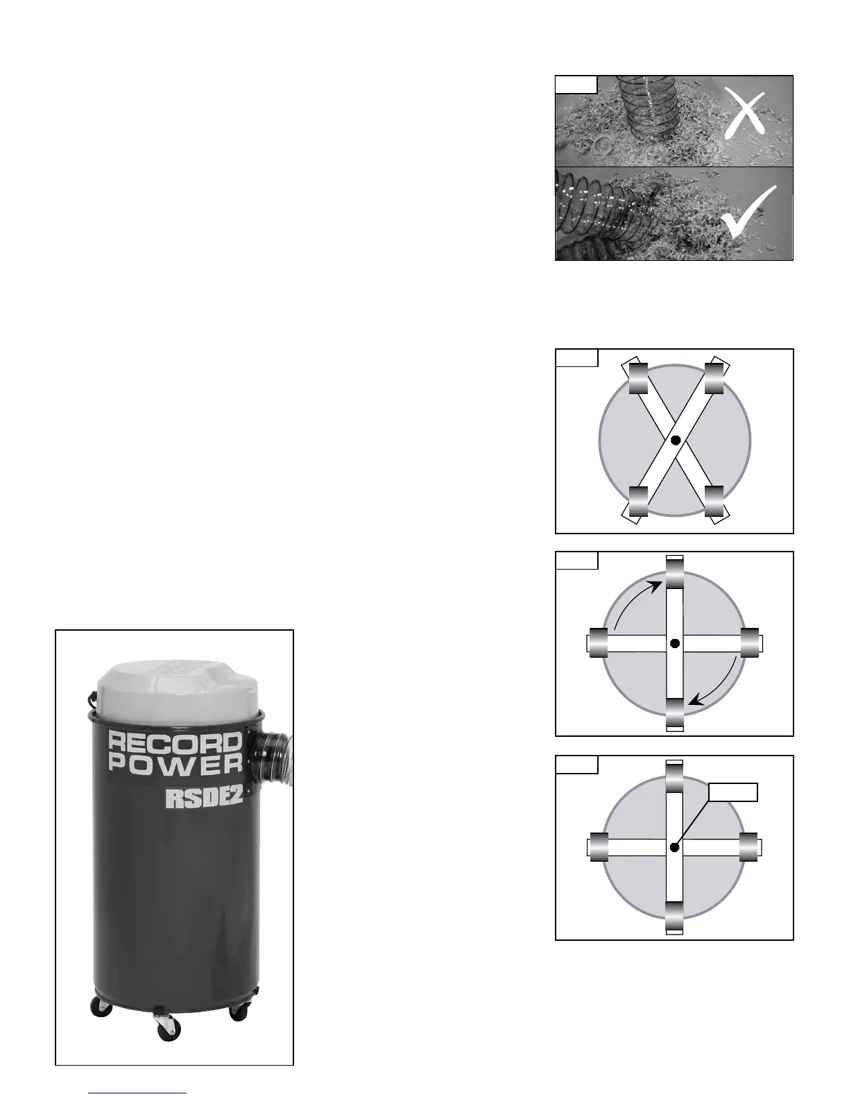
Important
• Always ensure that the end of the 102mm diameter flexible hose is not completely covered or blocked or
the machine may be ‘pulled’ suddenly towards the end of the hose (see Fig 5.1).
• The 102mm diameter flexible hose is intended mainly for connection to woodworking machinery to collect
sawdust and shavings.
• For cleaning purposes we recommend the use of the 32mm diameter flexible hose
(optional extra - part no. DX1500B).
• If the 102mm diameter hose is used for cleaning always ensure that the hose is angled as
shown in Fig. 5.1.
5. Assembly & Operation of RSDE1, RSDE2 & DX4000
Fitting RSDE/B wheel kit to the RSDE2
1. Remove the head unit from the body.
2. Turn the body upside down so the open end is resting on the floor.
3. Place the wheel kit on the body with the castors facing up.
4. To easily position the wheel kit in place it is recommended to firstly have the wheel kit in an
‘X‘ position. (Fig. 5.2)
5. Now move the wheel kit to be evenly spaced around the base of the body (Fig. 5.3) and the wheels will
become secured to the body of the extractor.
6. Finally tighten the hex nut in the middle of the wheel kit to eliminate movement.
7. Stand the body on the castors and attach the head unit once again.
Fig. 5.2
Fig. 5.3
Fig. 5.4
Hex Nut
Fig. 5.1