EasyManua.ls Logo

RectorSeal SAFE-T-SWITCH SS3 - User Manual

RectorSeal SAFE-T-SWITCH SS3
3 pages
Print Icon
To Next Page IconTo Next Page
Loading...
Description
Safe-T-Switch® Model SS3 specially designed mounting bracket mounts firmly over the edge of most drain
pans. The patented magnetic reed switch and slim profile can be installed on primary or auxiliary drain
pans. The SS3 switch is easily removed for cleaning and servicing.
US Patent No. 6,698,215
Component List: (See page 3)
(1) Bracket
(2) Stem assembly (includes Float, Tag, and Stem with wire)
(3) Thumb Screw (with 5/16 UNF thread)
(4) Warning Sticker (not shown)
Code Size Qty. per Case Lbs. per Case Cubic Ft per Case
97089
Safe-T-Switch SS3
24 5 0.73
Packaging
Maintenance
Inspect, clean and test this device at least every 30 days and following every cleaning of the drain line. 1. Clear debris or any other obstacles around the
Stem Subassembly. 2. Check for any damage. If damage is observed, replace this product with a new one. 3. Test switch function by following Step 6-7 in the
AUXILIARY DRAIN PAN INSTALLATION” section below. If this product failed function test, replace it with a new one.
Wiring
1. Disconnect power to A/C unit at the main panel prior to performing electrical work.
2. If not present, it is recommended that an inline fuse be installed to protect 24-volt circuit and
time delay be congured to avoid rapid cycling of equipment. 3. Locate the 24-volt thermostat
cable entering the air handler unit. 4. Disconnect or cut the red wire and connect to switch lead
using wire nut. Connect other switch lead to air handler terminal. Incorporating switch in red circuit
shuts down entire unit. If placed in the yellow circuit, fan continues to run (to inhibit mold growth
during long absences.) 5. Reconnect power to the A/C unit.
(Fig. 4)
To Switch
Red
White
Green
Yellow
From Thermostat
Wire Nut
Specications
24-Volts A/C, Maximum 1.25 Amp. Carrying Capacity, 6ft., 18 AWG Lead Wires.
PRODUCT DATA SHEET
Page 1 of 3
SAFE-T-SWITCH
®
SS3
For primary and auxiliary drain pans
Question and Answer IconNeed help?

Do you have a question about the RectorSeal SAFE-T-SWITCH SS3 and is the answer not in the manual?

Summary

Product Description

Product Specifications

Product Maintenance

Wiring Instructions

Installation Instructions

Auxiliary Drain Pan Installation

Detailed steps for installing the SS3 switch in auxiliary drain pans, including bracket attachment and float positioning.

Important Safety Information

Limited Warranty

Overview

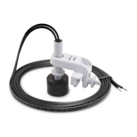
The RectorSeal Safe-T-Switch® SS3 is a safety device designed for use in primary and auxiliary drain pans of air conditioning (A/C) units. Its primary function is to detect rising water levels in the drain pan and, when a predetermined level is reached, to shut down the A/C unit to prevent overflow and potential water damage. This device utilizes a patented magnetic reed switch and a slim profile, making it suitable for installation in various drain pan configurations.

Function Description:

The Safe-T-Switch SS3 operates by detecting the presence of water in the drain pan. It consists of a bracket, a stem assembly (including a float, tag, and stem with wire), and a thumb screw. The bracket firmly attaches to the edge of the drain pan. The stem assembly, with its float, is positioned to allow the float to rise with the water level. When the water level in the drain pan rises to a critical point, the float lifts, activating the magnetic reed switch within the stem assembly. This activation sends a signal that interrupts the 24-volt circuit of the A/C unit, causing it to shut down. This prevents the drain pan from overflowing and mitigates the risk of water damage to the surrounding area. The switch can be wired into either the red (thermostat) circuit to shut down the entire unit or the yellow (fan) circuit to allow the fan to continue running, which can help inhibit mold growth during long absences. The device is easily removable for cleaning and servicing.

Important Technical Specifications:

  • Voltage: 24-Volts A/C
  • Maximum Carrying Capacity: 1.25 Amp
  • Lead Wires: 6 feet, 18 AWG
  • Compatibility: Works with 1-2” deep drain pans
  • Circuit Type: Class 2 (thermostat) circuit only
  • Patent: US Patent No. 6,698,215
  • Certifications: cULus Listed, IND. CONT. EQ. 75MF, UL 508

Usage Features:

  • Easy Installation: The specially designed mounting bracket allows for firm attachment over the edge of most drain pans. The thumb screw secures the bracket in place.
  • Adjustable Sensitivity: The stem subassembly can be moved up or down to adjust the switch's sensitivity to water levels, ensuring the A/C unit stops before the pan overflows.
  • Versatile Wiring Options: Can be wired to either the red circuit to shut down the entire A/C unit or the yellow circuit to keep the fan running, offering flexibility based on user preference and application needs.
  • Slim Profile: Its compact design allows for installation in both primary and auxiliary drain pans without obstructing other components.
  • Removable for Servicing: The switch is designed for easy removal, facilitating cleaning and maintenance.
  • Warning Sticker: Includes a warning sticker to be placed on a visible surface of the air handler or condenser unit, reminding users of the device's presence and function.
  • Component List: The device includes a bracket, stem assembly (float, tag, stem with wire), thumb screw (5/16 UNF thread), and a warning sticker.

Maintenance Features:

  • Regular Inspection: It is recommended to inspect, clean, and test the device at least every 30 days and after every cleaning of the drain line.
  • Debris Clearance: Users should clear any debris or obstacles around the stem subassembly to ensure proper float movement.
  • Damage Check: Periodically check for any damage to the device. If damage is observed, the product should be replaced.
  • Function Test: The switch function can be tested by lifting the float while the A/C unit is running to confirm it stops the unit. Alternatively, filling the pan with water should cause the float to rise and the A/C unit to stop before overflow.
  • Easy Cleaning: The design allows for easy removal of the switch, simplifying the cleaning process.

Safety Information:

  • Always disconnect power to the A/C unit at the main panel before performing any electrical work to prevent electric shock.
  • Installation must strictly adhere to the manufacturer's instructions and all applicable local plumbing, drainage, and electrical codes.
  • Use only in Class 2 (thermostat) circuits, not exceeding 24-volts and 1.25 amps, to avoid damage or fire hazards.
  • The device will not detect clogs upstream from its installation point.
  • An inline fuse and time delay are recommended to protect the 24-volt circuit and prevent rapid cycling of equipment.
  • This product is intended for use with water only and should not be used in the presence of flammable liquids or vapors.
  • Refer to the appropriate HVAC equipment operation manual before installation.
  • Do not use on dual compressor systems.

RectorSeal SAFE-T-SWITCH SS3 Specifications

General IconGeneral
BrandRectorSeal
ModelSAFE-T-SWITCH SS3
CategoryTV Mount
LanguageEnglish