-2-
Drawing No. LP0951D Released 2017-10-31
3.77
(95.8)
3.77 (95.8)
0.45
(11.4)
2.82 (71.5)
3.58 (91.0)
3.58
(91.0)
3.58
(91.0)
24
22
21
20
19
18
17
16
15
14
13
12
10
9
8
6
7
5
4
3
1
2
11
23
36
35
34
33
32
31
30
29
28
27
26
25
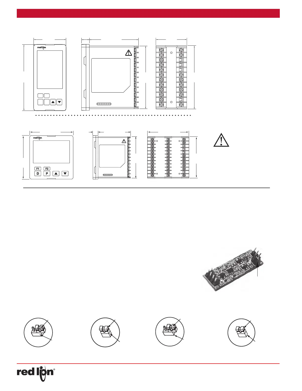
DIMENSIONS In inches (mm) - 1/4 DIN
13
14
16
15
18
17
19
20
21
22
23
24
1
2
3
4
5
6
7
11
10
9
8
12
3.77
(95.8)
(11.4)
0.45
2.82 (71.5)
(44.5)
1.76
(91.5)
3.60
3.60
(91.5)
(48.0)
1.89
F1
F2
DP
DIMENSIONS In inches (mm) - 1/8 DIN
PANEL CUT-OUT
PANEL CUT-OUT
CAUTION: Risk of Danger.
Read complete instructions prior to
installation and operation of the unit.
SAFETY SUMMARY
All safety related regulations, local
codes and instructions that appear in
the manual or on equipment must be
observed to ensure personal safety
and to prevent damage to either the
instrument or equipment connected to
it. If equipment is used in a manner not
specified by the manufacturer, the
protection provided by the equipment
may be impaired.
Do not use the controller to directly
command motors, valves, or other
actuators not equipped with
safeguards. To do so can be potentially
harmful to persons or equipment in the
event of a fault to the controller. If
redundant safeguards are not in place,
an independent and redundant
temperature limit indicator with alarm
outputs is strongly recommended.
SETTING THE JUMPERS
The PXU controller has input type jumpers that must be checked and/
or changed prior to applying power. The following Jumper Figures show
an enlargement of the jumpers.
To access the jumper, locate the two latches located on top and
bottom of the front of the unit. Starting with the top latch, insert a small
flat-blade screwdriver between the case latch and bezel while using your
thumb to push out on the bezel until the latch is disengaged. Repeat this
process with the bottom latch. After the latches are disengaged, using
the flat-blade screwdriver, gently pry out on the bezel in several areas
until the unit releases from the case.
Current Input
When Input Type is selected as one of the two current input types
(0-20 or 4-20), the current input jumper must be installed.
After removing the unit from the case as described, look for the
Current Input Jumper located close to the pc board area that connects
to the input terminals. For a current input type, position the jumper
across both pins. If input type is anything other than a current input,
position the jumper on only one pin. The current input jumper is factory
set for Temperature and Voltage input types.
Remote Input
When Remote Input Type (RmtP) is selected as one of the voltage
input types (0-5, 1-5, or 0-10), the current input jumper must be removed.
After removing the unit from the case as described, look for the
Remote Input option card. This card has REMOTE silk screened on it. It
may be necessary to remove a sticker to positively identify. Remove the
Remote Input option card and locate the 2 pin jumper on the bottom side
of the card. For a voltage input type, position the jumper on only 1 of the
2 pins. If Remote Input type is a current input type, position the jumper
on both pins. The Remote Input Type input jumper is factory set for
current input (0-20, 4-20).
JUMPER
PIN HEADER
JP8
FACTORY SETTING
Thermocouple, RTD
or Voltage Input
JUMPER
PIN HEADER
JP8
Current Input
(4-20 mA or 0-20 mA)
JUMPER
PIN HEADER
Voltage Input
(0-5, 1-5, or 0-10 VDC)
JUMPER
PIN HEADER
Current Input
(4-20 mA or 0-20 mA)
Remote Input
Jumper
 Loading...