Do you have a question about the red lion T48 and is the answer not in the manual?
General safety precautions and warnings for operating the controller.
Instructions for mounting the controller into a panel, including cutout dimensions.
Guidelines for stacking units and procedures for removing/installing the bezel.
Recommendations for minimizing electromagnetic interference during installation.
Details on making electrical connections, including signal and power wiring.
Specific instructions for connecting thermocouple and RTD sensor inputs.
Instructions for connecting AC or DC power supply to the controller.
Information on connecting Form-A relay outputs for control or alarm functions.
Details on connecting logic/SSR and triac outputs for control applications.
Wiring instructions for the heater current monitor option.
Wiring guidelines for the remote setpoint input signal.
Wiring for linear DC analog output signals.
Instructions for wiring the programmable user input terminal.
Table detailing terminal assignments for specific T48 models.
Terminal assignments for T48 models with RS485 or analog output.
Terminal assignments for all P48 controller models.
Diagram and explanation of connecting controllers to a host computer via RS-485.
Guide to selecting output range jumpers for main and second linear DC outputs.
Explanation of the functions of each front panel button.
Steps taken by the controller upon power application and initial display.
General approach to programming controller settings from the factory.
Essential parameters to verify or change for basic controller operation.
Steps for configuring serial communication parameters for setup.
How to configure the controlling method after setup.
Table showing valid combinations for heat (O1) and cool (O2) output modes.
Description of the normal operating display and how to navigate.
Access and modification rules for protected parameters.
Access and modification rules for unprotected parameters.
Access and operation of hidden functions, requiring unlock.
Navigating through configuration modules for setup.
Details of parameters viewable in the secondary display.
Describes how front panel access can be limited via lockouts or codes.
List and description of parameters accessible in unprotected mode.
Parameters accessible and modifiable in protected mode.
Functions and parameters available in the hidden mode.
Overview of accessing and navigating through configuration modules.
Detailed parameters for configuring T48 input types and scaling.
Selecting the signal input type for voltage or current.
Setting the decimal point for display parameters.
Adjusting rounding for display stability and readings.
Configuring digital filter and display update rate for signal stability.
Procedures for scaling input signals to display values.
Parameters affecting control output (O1) and linear DC output behavior.
Settings to limit operator access to parameters and modes.
Configuration options for alarm actions, reset, and values.
Parameters for configuring the cooling output (O2) function.
Settings for serial communication parameters like baud rate and address.
Configuration for remote setpoint input, filtering, and transfer options.
Configuring response for switching between local and remote setpoints.
Configuration for the second linear DC analog output range and scaling.
Includes controller calibration and factory reset functions.
Table to record T48 input parameter settings.
Table to record P48 input parameter settings.
Table to record output parameter settings.
Settings to limit operator access to parameters and modes.
Configuration options for alarm actions, reset, and values.
Parameters for configuring the cooling output (O2) function.
Explanations of input parameters for T48 models.
How to program setpoint ramping to control process changes.
Functions and programming for the user input terminal.
Selecting the signal input type for voltage or current.
Setting the decimal point for display parameters.
Adjusting rounding for display stability and readings.
Configuring digital filter and display update rate for signal stability.
Procedures for scaling input signals to display values.
Setting display values for scaling points.
Setting input signal values for scaling points.
Defining high and low limits for setpoint values.
How to program setpoint ramping to control process changes.
Functions and programming for the user input terminal.
Setting the cycle time for time-proportioning outputs.
Configuring heating (reverse) or cooling (direct) action for outputs.
Setting safe minimum and maximum output power limits.
Defining output behavior on sensor failure.
Adjusting filtering for output power to reduce activity.
Setting hysteresis to prevent output chatter in ON/OFF control.
Selecting code for auto-tune to achieve desired dampening.
Selecting the output range for the main linear DC output.
Selecting the variable for the main linear DC output retransmission.
Setting the update time for the main linear DC output.
Defining scaling points for the main linear DC output.
Restricting visibility of parameters in the secondary display.
Locking parameters for protected mode access.
Locking parameters for hidden mode functions.
Configuring alarm action modes and types.
Specific alarm for heater current monitor failure detection.
Visual representation of absolute high-acting alarm behavior.
Visual representation of deviation high-acting alarm behavior.
Configuration of automatic or manual alarm reset actions.
Function of standby delay to suppress alarms during power-up.
Setting absolute or relative values for alarms.
Setting hysteresis to prevent alarm output chatter.
Setting the cycle time for the cooling output.
Defining the gain of the cooling band relative to heating.
Defining overlap or deadband between heating and cooling outputs.
Settings for serial communication parameters like baud rate and address.
Configuration for remote setpoint input, filtering, and transfer options.
Specifications for heater current monitor input, accuracy, and alarm modes.
Configuration for the second linear DC analog output range and scaling.
Includes controller calibration and factory reset functions.
How to operate the controller in manual mode for direct output control.
Operation of ON/OFF control for a single output with hysteresis.
Using heat (O1) and cool (O2) outputs together in ON/OFF control.
How the controller automatically determines PID settings.
Step-by-step guide to starting the auto-tune function.
Specific auto-tune procedure for heat/cool systems.
Procedure for tuning cascaded controller systems.
Definition and explanation of the proportional band parameter.
Definition and explanation of the integral time parameter.
Definition and explanation of the derivative time parameter.
Adjusting output power to eliminate steady-state errors.
Guidance on adjusting PID parameters for process control.
Further guidance on PID adjustments and process response.
Step-by-step procedure for manually tuning PID parameters.
How to use a remote analog signal to change the setpoint value.
Overview of using two controllers for cascade control loops.
How the RS-485 interface enables two-way communication.
Information on the SFCRM software for configuration.
Configuring serial communication format via front panel.
How to construct command strings for communication.
Rules for sending numeric data in commands.
Assigning unique addresses for controllers on a serial bus.
Reference table for command codes used in serial communication.
Explanation of command terminator characters and their effects.
Table mapping register combinations to byte selections for block reads.
Explanation of the automatic setpoint ramping feature.
Using periodic setpoint writes for host-controlled setpoints.
Precautions for writing setpoint values to E²PROM memory.
Register explanation for heater current status.
Register explanation for the status of discrete alarm outputs.
How data is transferred over serial communication channels.
Explanation of start bits and data bits in serial transmission.
Function of parity bits in serial error detection.
Role of the stop bit in serial transmission.
Understanding timing restrictions for serial commands.
Detailed byte format for full field serial transmissions.
Byte format for abbreviated serial transmissions.
Checklist for resolving serial communication interface problems.
Troubleshooting 'SENS' display message indicating range issues.
Troubleshooting display messages indicating range issues.
Troubleshooting display messages indicating range issues.
Troubleshooting shorted RTD probe condition for T48.
Diagnosing and resolving sluggish or unstable control performance.
Troubleshooting display messages indicating range issues.
Description of the controller's output board and its function.
Step-by-step instructions for replacing the output board.
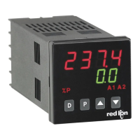
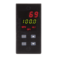
Details on the controller's dual 4-digit displays and messages.
Electrical power requirements for AC and DC versions.
Information on front panel controls and external user input.
Details on signal input sample period and response time.
Physical dimensions and panel cutout information.
Specifications for thermocouple input types and accuracy.
Specifications for RTD input types and accuracy.
Accuracy specifications for P48 voltage and current inputs.
Details on user input impedance, functions, and response time.
Procedures to verify accuracy of mV, thermocouple, and RTD inputs.
Procedure to check P48 voltage input accuracy.
Procedure to check P48 current input accuracy.
Procedure to check remote setpoint input signal accuracy.
Procedure to check heater current input accuracy.
Explanation of the E-CL error flag and its resolution.
Procedure for calibrating millivolt inputs.
Procedure for calibrating thermocouple cold junction compensation.
Procedure for calibrating RTD resistance inputs.
Calibrating the main and second linear DC analog outputs.
Procedure for calibrating the remote setpoint input.
Procedure for calibrating the heater current input.
Calibrating the main and second linear DC analog outputs.
Procedure for calibrating the remote setpoint input.
Calibrating voltage and current input sources.
Possible causes and remedies for no display issues.
Troubleshooting general controller non-operation.
Troubleshooting defective front panel button error.
Troubleshooting internal controller problems.
Troubleshooting parameter loss due to noise spikes.
Troubleshooting calibration loss due to noise spikes.
Troubleshooting display value exceeding range issues.
Troubleshooting open sensor condition for T48.
Troubleshooting 'SENS' display message indicating range issues.
Troubleshooting display messages indicating range issues.
Troubleshooting display messages indicating range issues.
Troubleshooting shorted RTD probe condition for T48.
Diagnosing and resolving sluggish or unstable control performance.
Troubleshooting display messages indicating range issues.
Description of the controller's output board and its function.
Step-by-step instructions for replacing the output board.
Details on the controller's dual 4-digit displays and messages.
Electrical power requirements for AC and DC versions.
Information on front panel controls and external user input.
Details on signal input sample period and response time.
Physical dimensions and panel cutout information.
Specifications for thermocouple input types and accuracy.
Specifications for RTD input types and accuracy.
Accuracy specifications for P48 voltage and current inputs.
Details on user input impedance, functions, and response time.
Specifications for relay output contacts, rating, and life expectancy.
Specifications for logic/SSR drive output ratings.
Specifications for triac output type, rating, and protection.
Control modes, output types, and auto-tune settings.
Specifications for alarm modes, reset, standby, and hysteresis.
Specifications for cooling or second output control.
Specifications for linear DC output range, accuracy, and resolution.
Specifications for remote setpoint input type, resistance, and range.
Specifications for heater current monitor input, accuracy, and alarm modes.
Details on RS485 interface, baud rate, data format, and isolation.
Electrical isolation ratings between different controller circuits.
Lists applicable certifications like CE, UL, and RoHS.
Operating and storage temperature, humidity, and vibration specs.
Describes the wire clamping screw terminals used for connections.
Describes the case material, bezel, and NEMA/IP ratings.
Part numbers and options for T48 models without specific outputs.
Part numbers and options for T48 models with RS485 or analog outputs.
List of available accessories for T48 controllers.
Part numbers and options for P48 process controllers.
List of available accessories for P48 controllers.
Terms and conditions of the product's limited warranty.
| Brand | red lion |
|---|---|
| Model | T48 |
| Category | Temperature Controller |
| Language | English |