SPECIFICATIONS AND DIMENSIONS
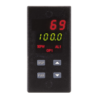
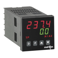
1. DISPLAY:Dual4-digit
Upper Process Display: 0.4" (10.2 mm) high red LED
Lower Auxiliary Display: 0.3" (7.6 mm) high green LED
Display Messages:
“OLOL” Measurement exceeds + input range.
“ULUL” Measurement exceeds - input range.
“OPEN” Open sensor is detected. (T48 only)
“SHrt” Shorted sensor is detected (RTD only)
“SENS” Measurement exceeds controller limits. (P48 only)
“...” Display values exceed + display range.
“-..” Display values exceed - display range.
LED Status Annunciators:
%P Lower auxiliary display shows power output in (%).
MN Flashing: Controller is in manual mode.
ON: Local Setpoint (Remote Setpoint option)
OFF: Remote Setpoint
DV Lower auxiliary display shows deviation (error) from
process setpoint or shows heater current.
O1 Main control output is active.
A1 Alarm #1 is active. (for AL1 Option)
A2 Alarm #2 is active OR
Cooling (Second) output (O2) is active.
2. POWER:
AC Versions: 85 VAC min. to 250 VAC max., 50 to 60 Hz, 8 VA max.
DC Versions:
DC Power: 18 to 36 VDC; 7 W
AC Power: 24 VAC ±10%; 50 to 60 Hz, 9 VA
3. CONTROLS: Four front panel push buttons for modification and setup of
controller functions and one external user input for parameter lockout or
other functions.
4. MEMORY: Nonvolatile E
2
PROM retains all programmable parameters
and values.
5. MAIN SIGNAL INPUT:
Sample Period: 100 msec
Response Time: Less than 300 msec typical, 400 msec max. (to within 99%
of final value w/step input; typically, response is limited to response
time of probe)
Failed Sensor Response (T48 only):
Main Control Output(s): Programmable preset output
Display: “OPEN”
Alarms: Upscale drive
Normal Mode Rejection: 40 dB @ 50/60 Hz
(improves with increased digital filtering).
-76-
Figure 43, Dimensions
DIMENSIONS In inches (mm)
PANEL CUT-OUT
 Loading...