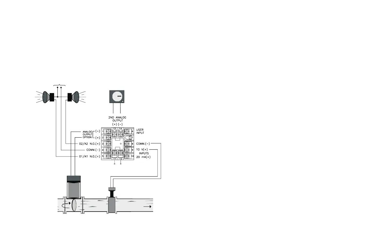
P48 Water Processing Application
A city water company needs to maintain a steady flow of water for their
customer needs. They have an existing 0 to 10 VDC flow transmitter to
measure the water flow. They need to control the water flow, have a high and
low alarm, and keep a recorded chart of the flow for later reference. The Main
Linear DC output of the P48 is used to control the position of water value to
maintain the desired flow setpoint value. The P48 relay outputs are
programmed to give a high flow alarm and a low flow alarm. With the Second
Linear DC output model, the flow measurement to the P48 can be
retransmitted to a chart recorder.
Process Requirements
Unprotected Parameters
ProP XX Calculated by Auto-Tune
Intt XX Calculated by Auto-Tune
dErt XX Calculated by Auto-Tune
AL-1 90.0 High alarm
AL-2 20.0
Low alarm
1-IN Configure Input Parameters
tYPE VOLt Voltage Input
dCPt 0.0 * Resolution
FLtr XX Calculated by Auto-Tune
dSP1 0.0 Input low value
INP1 0.00 Low display value
dSP2 10.0 Input high value
INP2 150.00 High display value
SPLO 40.0 Setpoint low limit
SPHI 80.0 Setpoint high limit
SPrP 0.0 * No ramping
INPt PLOC * User input program lock
2-OP Configure Output Parameters
CYCt 0 Disable O1 output
The remaining parameters in this module are set to factory settings.
4-AL Configure Alarm Parameters
Act1 A-HI Set 01/A1 for control output
rSt1 LAtC Manual reset
Stb1 yes Disable alarm during power-up
AL-1 90.0 Set 90.0 gal/min high alarm value
Act2 A-LO Set alarm #2 for deviation band from setpoint
rSt2
LAtC Manual reset
Stb2 yes Disable alarm during power-up
AL-2 20.0 Set 20.0 gal/min low alarm value
AHYS 5.0 Alarm activation hysteresis
8-A2 Configure Second Analog Parameter
A2tP 4-20 4-20 mA retransmitted
A2LO 0.0 Display low value
A2HI 150.0 Display high value
* Factory Settings
-68-
CHART
RECORDER
HIGH
ALARM
LOW
ALARM
WATER FLOW
ALARM
POWER
+
-
CONTROL
VALVE
FLOW
SENSOR
UNIT POWER
Figure 40, Water Processing Application
 Loading...