27
MAX 1,5m
b
b
b
6-ASSEMBLY
Technical Dept. - All rights reserved - Reproduction is prohibited
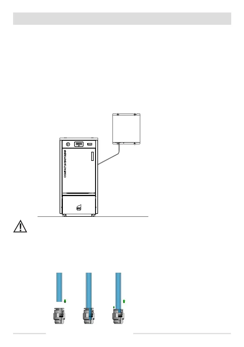
Connect compressor “A” to the boiler as follows:
• Take out compressor unit “A” from packaging 2
• Take the supplied gasket “e” and secure it to the sheet metal inside the compressor unit where it touches the boiler to avoid potential
vibration (see picture on previous page)
• Before securing the compressor to the boiler, remove the polystyrene in position “f”
• Take the four screws supplied and secure compressor “A” to the boiler
• remove knockout hole “d” from the panel at the back of the boiler
• take the ue of compressor “b” and insert it all the way in solenoid valve “c”
The compressor unit can also be xed to the wall to reduce the space taken up by the boiler.
To do this, you must:
• take 4 3.5 mm screws and Fischer plugs (not supplied)
• bring the compressor unit towards the wall and trace a mark with a pencil where you need to create the 4 holes
• drill the holes
• x the compressor to the wall with the 4 screws.
Caution!! the compressor pipe is not more than 1.5 metres long, which means you need to determine the position of
the compressor unit based on this measurement.
INSERTING / REMOVING THE COMPRESSOR PIPE
Mounting pipe “b”
• insert pipe “b” (compressor pipe) into the tting and push it all the way in.
Removing pipe “b”
• Exert a slight pressure on the extractor ring by taking out pipe “b” from the body of the tting at the same time.
 Loading...