11
Fig 6.5
6.4 Switched 24V Outputs:
These terminals have 24V DC present when the corresponding zone is set “ON”.
These may be used to operate something like an external relay used to turn on a solenoid, a lunch bell, etc.
(NOTE: The maximum current draw per output is about 120 milliamps (internally polyswitch protected), so it is advisable
to run external 24V DC relays instead of trying to drive a 24V DC device directly from these outputs. See Fig 6.2 for an
example of this).
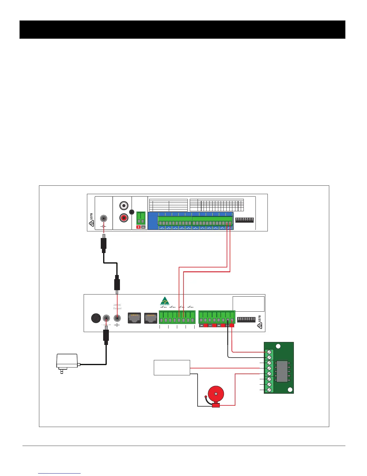
6.5 Closing Contacts:
These contacts “close” when the output zone is set “ON”. These can be used to trigger devices such as the Altronics
A 1741MP3 Message player.
Fig 6.5 demonstrates an example of how to connect the A 1708 to the A 1741. A 24V DC plugpack is used to power the
A 1708, the 24V DC output of the timer is then fed into the A 1741 using a power lead with 2.1mm DC connectors such
as the Altronics P 6717. Thus removing the need for another plugpack to power the message player.
The Zone 1 switched output of the timer is then used to trigger a 24V DC bell. As the current draw of the Bell is more
than 120mA a relay board is used to switch an external power supply. The Altronics S 4444 24V Relay Board as shown is
an inexpensive and easily installed option designed for this purpose.
In the example shown the Zone Output 2 closing contact of the timer is connected to the Input 1 trigger of the message
player. When Zone 2 is activated by the timer, message 1 of the message player will be played.
4
L
R
Line Out
12-30V DC
Switched
Out
12-30V DC
IN
1
www.altronics.com.au
Manufactured in Australia
By Altronic Distributors Pty. Ltd.
1 2 3 4 5 6 7 8
2
3567
8
Alert
Cancel
DIP Switch Settings
ON OFF
1
Triggers momentary Triggers alternate
2
Alert/Evac ON
Not Used
SW
TRIGGER OPERATION & ALERT/EVAC SETTINGS
DIP Switches
Evac
Triggers
Close
Contacts
to
Trigger
5
0 1 0 1 0 1 0 1 0 1 0 1 0 1 0 1
6
0 0 1 1 0 0 1 1 0 0 1 1 0 0 1 1
7
0 0 0 0 1 1 1 1 0 0 0 0 1 1 1 1
8
0 0 0 0 0 0 0 0 1 1 1 1 1 1 1 1
Delay
(Sec.)
OFF
30
60
90
120
150
180
210
240
270
300
330
360
390
420
450
AUTO ALERT TO EVAC SWITCHOVER TIMER SETTINGS. 0 = OFF. 1 = ON.SW
3
Front switches active Front switches de-activated
4
Alert/Evac OFF
+
–
+
4 3 2 1
4 3 2 1
24V Switched Out
DIP Switch Settings
SW ON
1
2
Station Edit Lockout Enabled
3
Edit Time Lockout Enabled
4
Clear Memory Lockout Enabled
Battery Backup On
www.altronics.com.au
Manufactured in Australia
By Altronic Distributors Pty. Ltd.
DIP Switches
Interface 1 Interface 2DC Fuse
M205
2 Amp
+
+
_
_
 Loading...