2
Fig 1
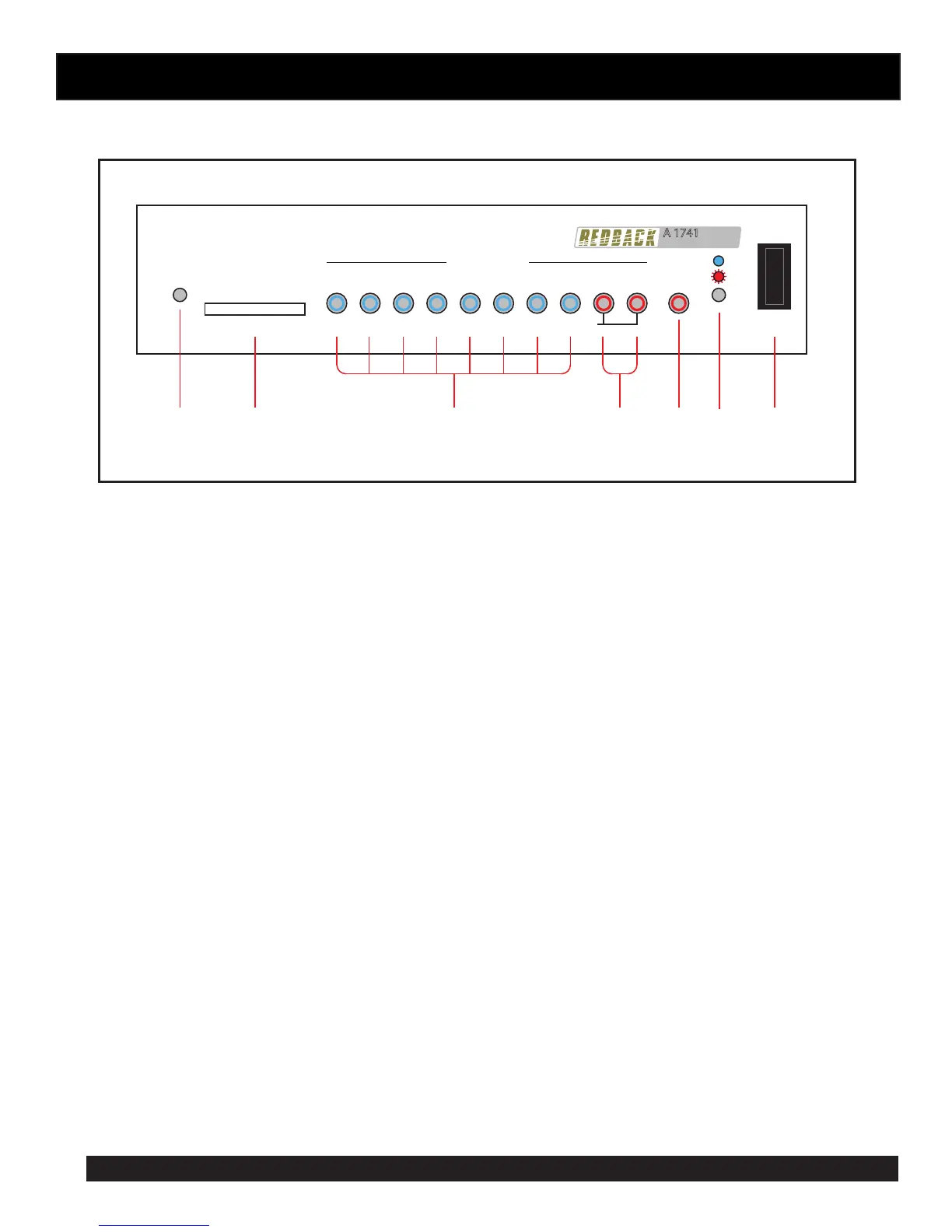
3.0 FRONT PANEL CONNECTIONS
Timer
Message Player
A 1741
Power
1 2 3 4 5 6 7 8 Alert Evac
Message Active
SD CARD
Cancel
Fault
On
16GB Maximum
Hold down the Alert or Evac button for 3 seconds to activate
Switches
Disabled
71 2 3 4 5 6
1 Switches Disabled Indicator
This LED illuminates when the front switches are set to be disabled via the DIP switches on the rear of the
unit. (See Fig 2 for DIP Switch location).
2 SD card slot
The SD card which has the messages (in MP3 format) to be played is inserted here. The SD card can be a
maximum of 16GB.
3 Message Active Switches and Indicators
These switches are used to trigger the messages 1-8. The LED’s inside the switches indicate when the
associated message is playing. The messages can also be activated by using the triggers on the rear of the
unit. (See Fig 2 for details.) NOTE : If DIP switch 3 on the rear of the unit is set to “OFF” the front switches
will not operate and the “Switches Disabled” LED will illuminate.
4 Alert and Evac Switches and Indicators
These switches are used to trigger the Alert and Evacuation tones (which conform to AS1670.4). The LED’s
inside the switches indicate when the associated message is playing. The tones can also be activated by using
the Alert and Evac triggers on the rear of the unit. (See Fig 2 for details.) NOTE : If DIP switch 3 on the rear
of the unit is set to “OFF” the front Alert and Evac switches will not operate and the “Switches Disabled”
LED will illuminate. The Alert and Evac tones can also be disabled from the rear triggers by setting DIP switch
2 to the “OFF” position. (See Fig 2 for details.)
5 Cancel Switch
Use this switch to cancel any MP3 which is playing. (This may need to be held down for 2 seconds to cancel).
The Cancel option can also be activated by using the Cancel trigger on the rear of the unit. (See Fig 2 for
details.) NOTE : If DIP switch 3 on the rear of the unit is set to “OFF” the front Cancel switch will not operate
and the “Switches Disabled” LED will illuminate.
6 Status Led
This LED indicates whether the unit is ON or has a Fault condition. If the LED is “steady blue” the unit is
receiving power. If the LED is “ashing red” then a fault has occured with the unit.
7 Power Switch
Used to turn the unit On or OFF.
 Loading...