ver. 5/2023
RedGrey ul. Główna 13, 47- 450 Krzyżanowice
tel. +48 32 414 75 44/ e-mail: biuro@redgrey.pl / www.redgrey.pl
4
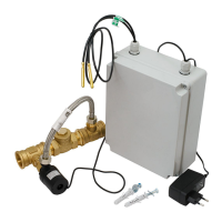
Bypass installation:
The included bypass must be installed in the supply or return on the pipe section between the buffer/DHW tank and heat pump.,
taking into account the correct flow direction. Both the flap and the pump body must be mounted horizontally for proper
function as in the picture below. It is also advisable to install the system in such a way that the pump connection hose is below
the level of the main pipe in order to allow easy de-aeration.
Careful and effective insulation of the pipeline outside will significantly extend the operating time of the system on
battery backup. If possible and depending on the device to be protected, you can also insulate the condenser.
Make sure that the bypass is well de-aerated and that there are no elements in the circuit that could block the flow of
the circulating pump in operation!
An example of the crrect bypass setting:
Examples of incorrect bypass setting:
Pump rotor vertical – difficult de-aerating.
Difficult hose de-aerating.
Risk of noisy flap operating.
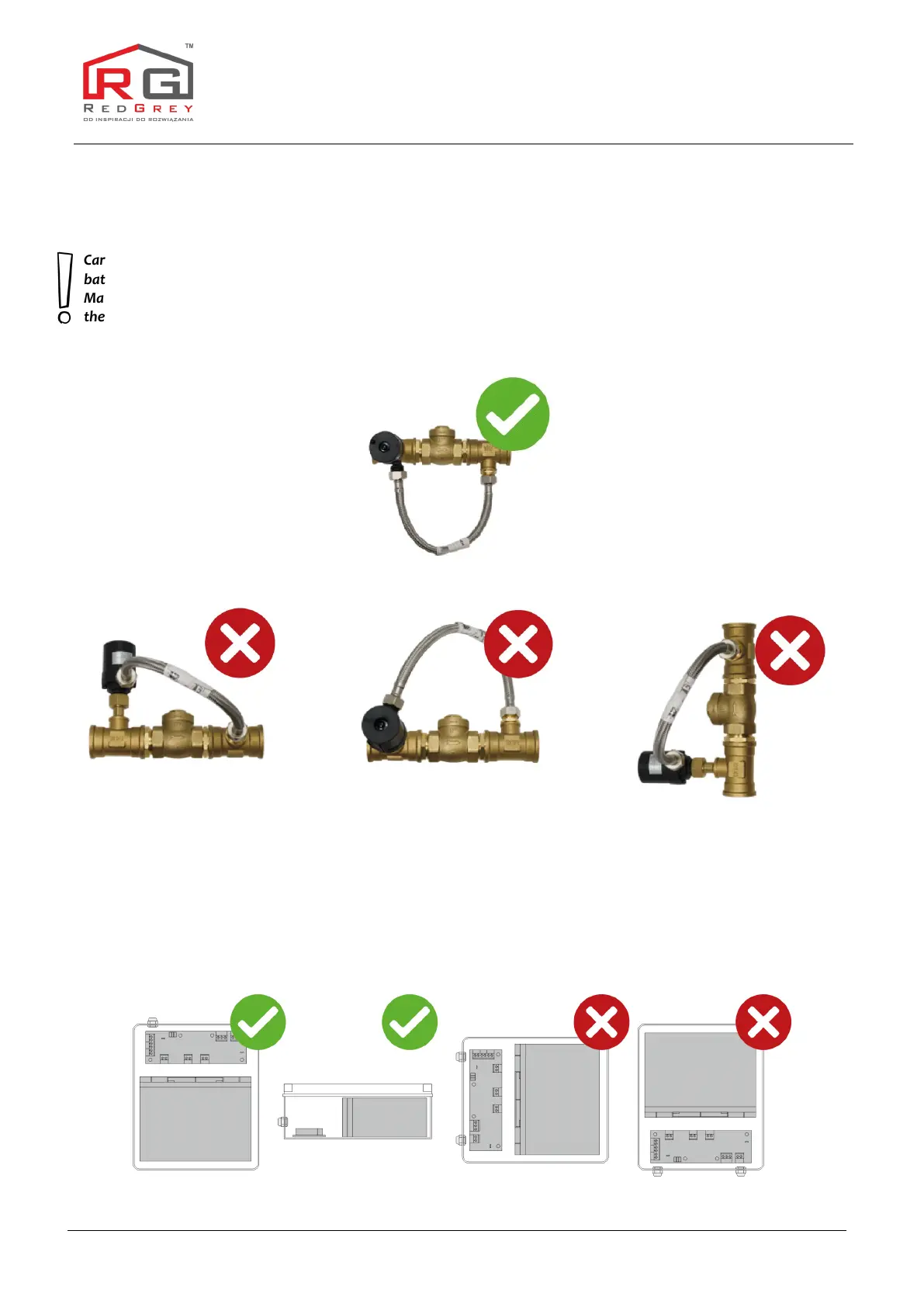
Supply modul installation:
Moduł zasilania pompy należy zawiesić na ścianie za pomocą kołków rozporowych z wkrętami zwracając uwagę na prawidłową
orientację montażową, tj. akumulator w dolnej części, a sterownik w górnej. W sterowniku zweryfikować i ewentualnie
podłączyć zasilanie pompy (PUMP) i czujniki temperatury T1 i T2 (IN1 i IN2). Następnie należy podłączyć wtyczkę akumulatora
(BATTERY) akumulatora oraz włożyć ładowarkę do gniazdka.
Supply module should be fixed to wall by using mounting screws,
according to picture below. Ensure that all wires are connected, like pump into „PUMP” socket, both sensors T1 and T2 into
“IN1” and “IN2” sockets. After that, battery plug should be inserted into „BATTERY” socket and than the charger connected to
a wall socket.
 Loading...