REFCO Manufacturing Ltd. Telefon +41 41 919 72 82
Industriestrasse 11 Telefax +41 41 919 72 83
CH-6285 Hitzkirch (Switzerland) Info@refco.ch www.refco.ch
Inspection and Maintenance
Evaporator / Coil Cleaning.
Testing
Inspect the filter for sediment and debris.
When handling pump during inspection and
maintenance, k
If cleaning is required, disconnect the filter
housing by rotating 80° Counter clockwise and
carefully separate (fig.9).
Inspect the Inlet Tube for dirt and blockages
and clean if required.
carefully pour clean water
eep Pump Assembly reasonably
upright and level to prevent any water spills
from entering the pump.
In some installations it may be possible to
service the pump while still attached to the
equipment. If necessary support the Pump
Assembly to prevent excessive strain on cables
and connections.
Using a small tool carefully lift the filter out of its
location and rinse under a tap with clean water.
If the O ring is disturbed, clean O ring and
mating surfaces and re-seat (fig.10).
Inside of the Sensor chamber check for debris
between the sensor plates . Clean gently with
a soft cloth or Q-tip (fig.11).
Clean the sealing surface and re-assemble the
Filter chamber onto the pump
Inspect the discharge tube for blockages and
kinks.
Inspect the Breather tube for positioning and
obstructions.
When using evaporator cleaning agents,
drain discharged liquid into a separate
container and flush with clean water. Do not
allow cleaning agents and dirt to drain into
Pump.
On new installations, flush installation debris
through condensate system into a bucket,
before connecting the pump. If possible
via the condensate
collection tray to check also the water drain
route.
Use a wash bottle if possible as these are more
controllable.
The pump should begin to pump until all, but
approximately 12mm / 1/2" of water is left
remaining.
Do not use detergents in servicing this product.
Do not scratch
sensitive surfaces.
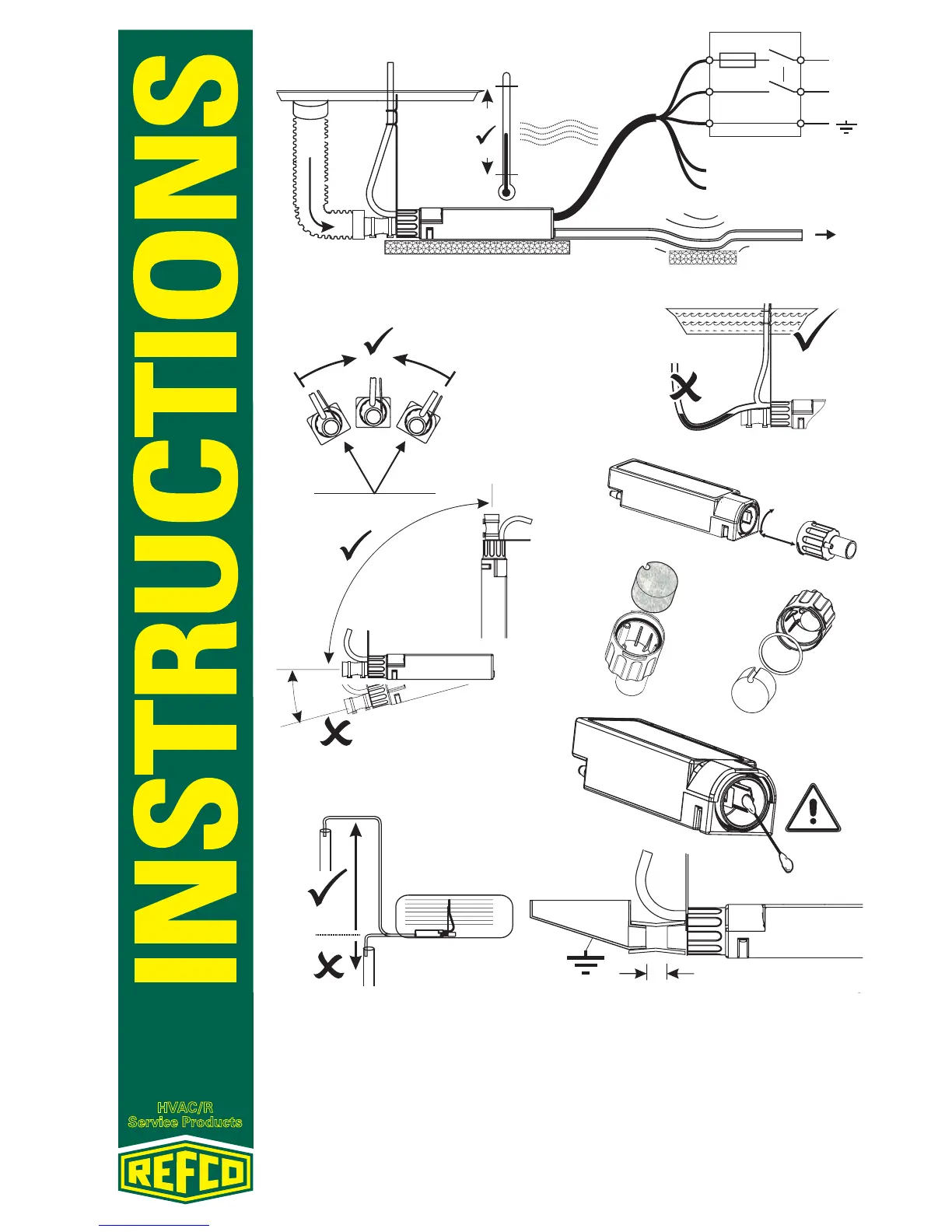
Installation
Location
This Pump is not submersible. Select a suitable location for the
pump within the equipment which is level (fig. 4 & 5) and not likely
to be disturbed in general use. Ensure the drain hose slopes
down directly to the pump without drooping and kinking (fig. 3).
Separate the Pump and Discharge Tube from panels and surfaces
with insulating foam rubber to further reduce noise transmission.
If
connecting directly to Earthed/ Grounded Metal Tray or pipes,
allow 15mm/ 5/8" distance between parts (fig.12).
Run discharge tubing to a suitable drain where it is unlikely to
freeze during operation. The highest point of the run must be less
than 49ft/ 15m above the Pump and not more than 0.3m(1ft)
below to avoid siphoning (fig. 7). Maximum tube length is 330ft/
100m. Take care not to pinch or kink the tubing. Secure or support
the discharge tube to reduce noise.
Push the rubber Inlet Connector onto the drain hose (fig. 3) or
collection tray stub. Secure with the cable ties provided.
Bend into position the breather support wire so tube end is above
collection tray if possible (fig.8).
WARNING! SWITCH OFF ALL SUPPLIES AT THE FUSE BOX
BEFORE MAKING CONNECTIONS TO THIS PUMP.
The installation must provide a suitable means for electrical
disconnection (fig.3).
Fuse Protection Required: Europe 5 Amp max.
European Cable: 0.75mm²
USA. Factory fitted cable is 18 AWG for equipment internal wiring
only.
Refer to National and Local Electrical Codes for fusing and
disconnection requirements.
The alarm relay is energised to make continuity during
normal operating conditions (break on fault).
Piping
Wiring
Alarm Relay
This pump requires an Earth/ Ground connection.
EUROPEAN
USA
Cable Colour Coding
BROWN L
LIVE PHASE
BLUE N
NEUTRAL
GREEN/YELLOW E EARTH
BLACK ALARM
RELAY
GREY ALARM
RELAY
Cable Colour Coding
BLACK L1
LIVE PHASE
WHITE L2
NEUTRAL
GREEN GROUND
ORANGE ALARM
RELAY
RED ALARM
RELAY
(PHASE 2, 220V
SYSTEM)
CAUTION: DISCONNECT ALL POWER SUPPLY BEFORE PERFORMING ANY
SERVICING OR MAINTENANCE. ONLY COMPETENT PERSONS SHOULD ATTEMPT TO
SERVICE THIS PRODUCT.
30°
30°
fig. 4
fig. 5
15M/ 49ft max
fig. 7
fig. 8
fig. 9
fig. 10
fig. 11
LIT-2500
fig. 12
15mm/ 5/8"
p2
p3
50°C
122°F
0 °C
32°F
SUPPLY
VOLTAGE
N
L
5A
Alarm or
Thermostat Circuit.
fig. 3
Inspection and Maintenance
Evaporator / Coil Cleaning.
Testing
Inspect the filter for sediment and debris.
When handling pump during inspection and
maintenance, k
If cleaning is required, disconnect the filter
housing by rotating 80° Counter clockwise and
carefully separate (fig.9).
Inspect the Inlet Tube for dirt and blockages
and clean if required.
carefully pour clean water
eep Pump Assembly reasonably
upright and level to prevent any water spills
from entering the pump.
In some installations it may be possible to
service the pump while still attached to the
equipment. If necessary support the Pump
Assembly to prevent excessive strain on cables
and connections.
Using a small tool carefully lift the filter out of its
location and rinse under a tap with clean water.
If the O ring is disturbed, clean O ring and
mating surfaces and re-seat (fig.10).
Inside of the Sensor chamber check for debris
between the sensor plates . Clean gently with
a soft cloth or Q-tip (fig.11).
Clean the sealing surface and re-assemble the
Filter chamber onto the pump
Inspect the discharge tube for blockages and
kinks.
Inspect the Breather tube for positioning and
obstructions.
When using evaporator cleaning agents,
drain discharged liquid into a separate
container and flush with clean water. Do not
allow cleaning agents and dirt to drain into
Pump.
On new installations, flush installation debris
through condensate system into a bucket,
before connecting the pump. If possible
via the condensate
collection tray to check also the water drain
route.
Use a wash bottle if possible as these are more
controllable.
The pump should begin to pump until all, but
approximately 12mm / 1/2" of water is left
remaining.
Do not use detergents in servicing this product.
Do not scratch
sensitive surfaces.
Installation
Location
This Pump is not submersible. Select a suitable location for the
pump within the equipment which is level (fig. 4 & 5) and not likely
to be disturbed in general use. Ensure the drain hose slopes
down directly to the pump without drooping and kinking (fig. 3).
Separate the Pump and Discharge Tube from panels and surfaces
with insulating foam rubber to further reduce noise transmission.
If
connecting directly to Earthed/ Grounded Metal Tray or pipes,
allow 15mm/ 5/8" distance between parts (fig.12).
Run discharge tubing to a suitable drain where it is unlikely to
freeze during operation. The highest point of the run must be less
than 49ft/ 15m above the Pump and not more than 0.3m(1ft)
below to avoid siphoning (fig. 7). Maximum tube length is 330ft/
100m. Take care not to pinch or kink the tubing. Secure or support
the discharge tube to reduce noise.
Push the rubber Inlet Connector onto the drain hose (fig. 3) or
collection tray stub. Secure with the cable ties provided.
Bend into position the breather support wire so tube end is above
collection tray if possible (fig.8).
WARNING! SWITCH OFF ALL SUPPLIES AT THE FUSE BOX
BEFORE MAKING CONNECTIONS TO THIS PUMP.
The installation must provide a suitable means for electrical
disconnection (fig.3).
Fuse Protection Required: Europe 5 Amp max.
European Cable: 0.75mm²
USA. Factory fitted cable is 18 AWG for equipment internal wiring
only.
Refer to National and Local Electrical Codes for fusing and
disconnection requirements.
The alarm relay is energised to make continuity during
normal operating conditions (break on fault).
Piping
Wiring
Alarm Relay
This pump requires an Earth/ Ground connection.
EUROPEAN
USA
Cable Colour Coding
BROWN L
LIVE PHASE
BLUE N
NEUTRAL
GREEN/YELLOW E EARTH
BLACK ALARM
RELAY
GREY ALARM
RELAY
Cable Colour Coding
BLACK L1
LIVE PHASE
WHITE L2
NEUTRAL
GREEN GROUND
ORANGE ALARM
RELAY
RED ALARM
RELAY
(PHASE 2, 220V
SYSTEM)
CAUTION: DISCONNECT ALL POWER SUPPLY BEFORE PERFORMING ANY
SERVICING OR MAINTENANCE. ONLY COMPETENT PERSONS SHOULD ATTEMPT TO
SERVICE THIS PRODUCT.
30°
30°
fig. 4
fig. 5
15M/ 49ft max
fig. 7
fig. 8
fig. 9
fig. 10
fig. 11
LIT-2500
fig. 12
15mm/ 5/8"
p2
p3
50°C
122°F
0 °C
32°F
SUPPLY
VOLTAGE
N
L
5A
Alarm or
Thermostat Circuit.
fig. 3
 Loading...