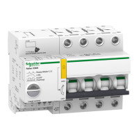
Installation
18
A9MA03EN 02/2012
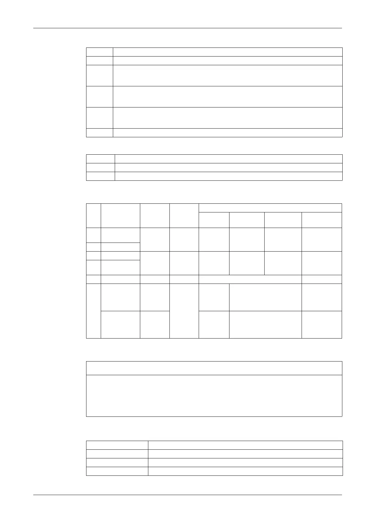
E interface I/O terminal block Ti24
F Isolated terminals
Connection Characteristics
Connection Diagrams
Minimum power recommended for the Reflex iC60 integrated control circuit breaker power supply
according to the number of poles:
Terminal Function
0 V 0 V DC power supply
O/C Indication of the position (open/closed) of the poles of the circuit breaker:
z O/C closed: the contacts are closed.
z O/C open: the contacts are open.
auto/OFF Indication of tripping of the circuit breaker:
z auto/OFF closed: the circuit breaker handle is in the auto position.
z auto/OFF open: the circuit breaker handle is in the OFF position.
Y3 Mode 1: centralized closing control on rising edge and opening control on falling edge
Mode 2: centralized closing control on rising edge and opening control on falling edge
Mode 3: centralized closing control on rising edge and opening control on falling edge
24 V 24 V DC power supply
Terminals Function
0.5...25 A Power
32...63 A Power
Item Terminal block Tightening
torque
Stripping
length
Wire size
Solid Flexible Flexible with
ferrule
2 cables
A Power supply
(230 V AC)
1 N.m 10 mm 1...10 mm² 1...6 mm² 0.5...4 mm² ≤ 2 x 1.5 mm²
≤ 2 x 2.5 mm²
B Inputs Y1/Y2
C Output O/C 0.7 N.m 8 mm 1...2.5 mm² 0.5...2.5 mm² 0.5...1.5 mm² ≤ 2 x 1.5 mm²
D Output
auto/OFF
E Ti24 interface – 10 mm 0.5...1.5 mm² –
F 0.5...25 A 2 N.m 14 mm 1...25 mm² 0.5..0.16 mm² ≤ 5 x 1.5 mm²
≤ 3 x 2.5 mm²
≤ 2 x 1.5 mm² +
≤1x2.5mm²
32...63 A 3.5 N.m 1...35 mm² 0.5...25 mm² ≤ 5 x 4 mm²
≤ 3 x 6 mm²
≤ 2 x 4 mm² +
≤1 x 6 mm²
NOTICE
RISK OF MALFUNCTION
z In three-phase applications, use the same phase to connect the power supply and inputs Y1 and Y2.
z Keep to the recommended minimum power for the Reflex iC60 integrated control circuit breaker
power supply.
Failure to follow these instructions can result in equipment damage.
Number of poles Power supply
2P 350 VA
3P 700 VA
4P 1350 VA