Installation
A9MA03EN 02/2012 19
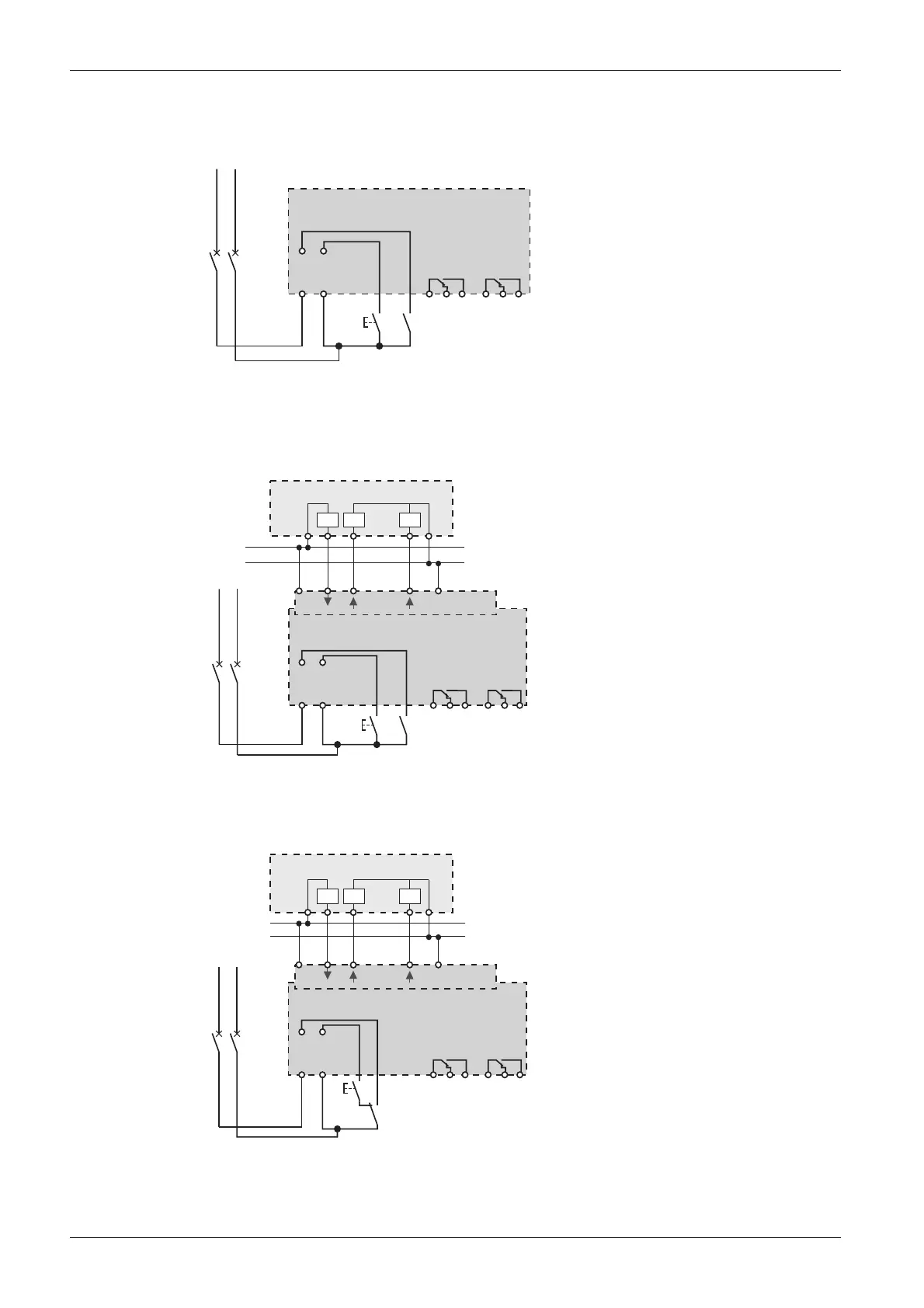
The following diagram illustrates connection of a Reflex iC60 integrated control circuit breaker, without
Ti24 interface, used in mode 1 or 2:
The following diagram illustrates connection of a Reflex iC60 integrated control circuit breaker, with Ti24
interface, used in mode 1, 2 or 3:
The following diagram illustrates connection of a Reflex iC60 integrated control circuit breaker, with Ti24
interface, used in mode 3:
NP
PN
Y1 Y2
11 12 14
O/C
21 22 24
auto/OFF
A9C5pppp
NP
PN
24 V c
PLC
24 V
auto/OFF
O/C 0V
0 V
In
In
Out
Y3
Ti24
Y1 Y2
11 12 14
O/C
21 22 24
auto/OFF
A9C6pppp
24 V c
0 V
In
Out
NP
PN
24 V
O/C 0V
Y3
Ti24
Y1 Y2
11 12 14
O/C
21
22 24
auto/OFF
A9C6pppp
auto/OFF
In
PLC