Use
26
A9MA03EN 02/2012
Operation is as follows:
z When input Y1 is at 0, input Y2 is operational (local control) and input Y3 (centralized control via Ti24)
is ineffective
z When input Y1 is at 1, input Y2 is ineffective (local control) and input Y3 (centralized control via Ti24)
is operational
z A pulse on input Y2 makes the Reflex iC60 circuit breaker switch alternately from Ready position
(contacts open) to closed position
z When input Y3 (Ti24) changes to 1, the Reflex iC60 circuit breaker switches to closed position
z When input Y3 (Ti24) changes to 0, the Reflex iC60 circuit breaker switches to Ready position
(contacts open)
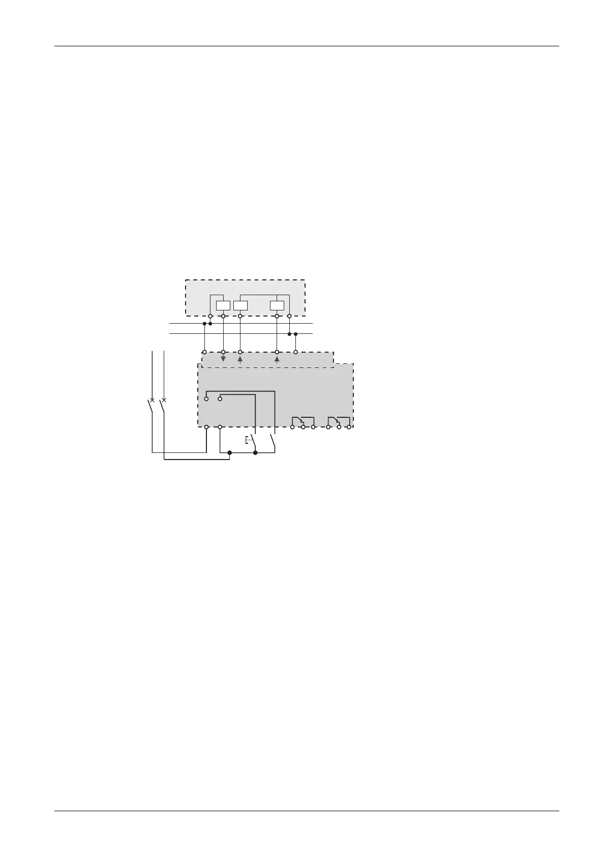
Connection diagram 2
The following connection diagram enables the Reflex iC60 circuit breaker to optionally use (depending
on the state of input Y1) the controls on input Y3.
The controls on input Y2 are still taken into account by the Reflex iC60 circuit breaker.
Mode 3 is used for centralized opening or closing of the circuit breaker and local override:
z Y1: centralized control enabled (Y1 = 1) or centralized control prohibited (Y1 = 0)
z Y2: local one-shot closing and opening control
z Y3: centralized closing control on rising edge and opening control on falling edge
NP
PN
24 V c
PLC
24 V
auto/OFF
O/C 0V
0 V
In
In
Out
Y3
Ti24
Y1 Y2
11 12 14
O/C
21 22 24
auto/OFF
A9C6pppp