Use
A9MA03EN 02/2012 25
Mode 3
Mode 3 can be used with 2 different connection diagrams.
The behavior of the control inputs is specific to each connection diagram.
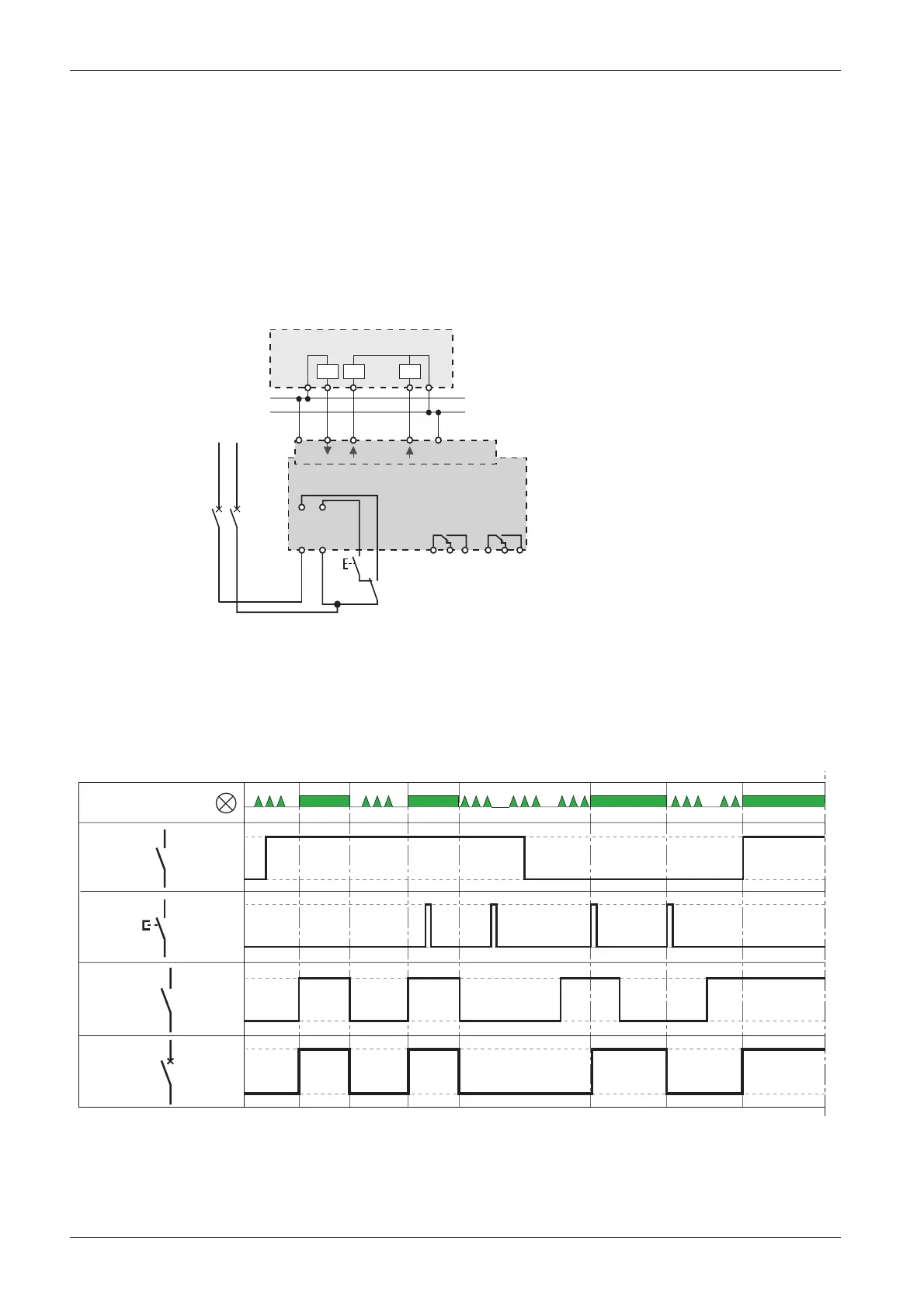
Connection diagram 1
The following connection diagram is based on a selector (input Y1) so that the Reflex iC60 circuit breaker
uses, in exclusive mode, the controls:
z On input Y2 (in this case, controls on input Y3 are ineffective)
z On input Y3 (in this case, controls on input Y2 are ineffective)
Mode 3 is used for centralized opening/closing of the circuit breaker and local override:
z local control selector (Y1 = 0) and centralized control (Y1 = 1)
z Y2: local one-shot closing and opening control
z Y3: centralized closing control on rising edge and opening control on falling edge
The following diagram shows mode 3 operation.
24 V c
0 V
In
Out
NP
PN
24 V
O/C 0V
Y3
Ti24
Y1 Y2
11 12 14
O/C
21
22 24
auto/OFF
A9C6pppp
auto/OFF
In
PLC
Y1
Y2
I. ON
Ready
Y3
(Ti24)
Reflex
iC60
on
off
on
off
on
off