Do you have a question about the Refrigeration Innovation Thermo-Simple 2 and is the answer not in the manual?
Details the power supply unit for the multi-node configuration.
Describes the junction box used for single temperature cases.
Outlines the power harness connecting components in a multi-node setup.
Lists available lengths and part numbers for spine cables.
Provides part numbers and lengths for temperature sensors.
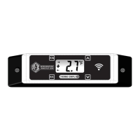
Identifies the display unit component (PN: TS2-DS).
Explains the specific power supply requirements for multi-node configurations.
Provides critical notes on connecting Thermo-Simple harnesses and cables to the junction box.
Details the function and connection point for the SPINE port on the junction box.
Details the function and connection point for the Thermo-Simple port on the junction box.
Details the power supply unit for single node configurations.
Describes the power harness for single temperature applications.
Describes the power harness for dual temperature applications.
Notes the unavailability of dual temp input on single temp power harness.
Identifies the display unit component (PN: TS2-DS).
Provides part numbers and lengths for temperature sensors.
Explains how the dual temperature power harness switches set-points based on case temperature.
Provides dimensional details for cut-out holes for 0.75" and 1" deep mounts.
Specifies the type of screws required for mounting the device.
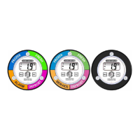
Explains the meaning of indicators like Incoming Data, Positive/Negative Temperature, and Outgoing Data.
Describes the numeral indicator showing Temperature, Set-Point, Address, or Status.
Identifies the temperature scale indicator on the display.
Details the function and operation of the magnetic switches on the TS.2 device.
Introduces basic switch functions for changing temperature scale or set-point.
Describes the F/C switch for temporarily changing temperature units or clearing display.
Describes the M/L switch for displaying active set-point or current alarm set point.
Explains the TS.2 function switch for advanced functions and settings.
Sets the default temperature display to Celsius or overrides defrost display.
Cycles through and selects alarm set-points, including dual temp modes.
Toggles the defrost function on or off, affecting display during non-set-point periods.
Assigns the next available network address for WiDAQ wireless systems.
Clears the device's network address and stops WiDAQ communication.
Manually assigns a network address, useful for device replacement.
Instructions on how to view the current set-point using the M/L switch.
Steps to change the current set-point using the TS.2 and M/L switches.
Instructions to enable or disable the defrost notification feature.
Addresses common problems like alarm modes, display errors, and power issues.
Explains the meaning of LED colors for BGA and GAR devices.
| Temperature Range | -50°C to 300°C |
|---|---|
| Accuracy | ±1°C |
| Resolution | 0.1°C |
| Display Type | LCD |
| Waterproof | IP67 |
| Battery Type | CR2032 |
| Battery Life | 1000 hours |