Do you have a question about the Refrigeration Innovation Thermo-Simple 1 version 2 and is the answer not in the manual?
Overview of multi-node setup, listing components like power supply, junction box, cables, sensors.
Specifics on the input and output of the power supply for multi-node configurations.
How to connect power supply or spine cable to the SPINE port, with warnings.
How to connect the power harness to the Thermo-Simple port, with warnings.
Lists components like power harness, mounting harness, display unit, and sensors for single node.
Specifications for the power supply used in single node configurations.
Details the two main components and their connection via spring contacts for installation.
Specifies screw types and lengths required for proper mounting plate and display unit engagement.
Critical clearances for #6 or #8 Low Profile Pan Head screws for mounting plate attachment.
Critical clearances for #4 x 3/16" Flathead Undercut Countersunk screws for display.
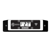
Description of display indicators like incoming/outgoing data, temperature, and scale.
How to use magnetic switches for control and what tools are needed.
Steps to unlock the display unit to change settings using magnetic switches.
Procedure to change the default temperature scale from Fahrenheit to Celsius.
How to enable or disable the defrost indicator ('dEF') on the display unit.
How to enable or disable the freeze alarm, which triggers below 33.5°F.
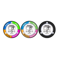
Details the available color schemes (BGA, GAR, No Color) and their visual states.
Explains the "ALA" flag, its display conditions, and how to clear the alarm state.
How dual temperature cases automatically switch set-points between 5.0°F and 40.0°F.
Describes different set-point states (below, at, above) and their corresponding LED colors.
How to adjust the defrost timer between 60 or 90 minutes for larger cases.
Details the 2-year warranty against defects in materials and workmanship.
| Brand | Refrigeration Innovation |
|---|---|
| Model | Thermo-Simple 1 version 2 |
| Category | Thermometer |
| Language | English |