Electrical Connections. The generator conduit box
has
a cable entry hole drilled on the side
of
the
connection box. To minimize the transmission
of
vibration,
it
is
essential that flexible cable
or
cc;:mduit
be used for
all
electrical entrance to the generator connection box. Refer to the connection
diagram supplied with the unit and/or the proper diagrams shown
in
this manual. Install
all
inter-component and external wiring
in
accordance with national and local electrical codes. Insure
that grounding (earthing)
of
the generator frame
and
other components and electrical systems is in
accordance with
all
applicable national and local codes and standards.
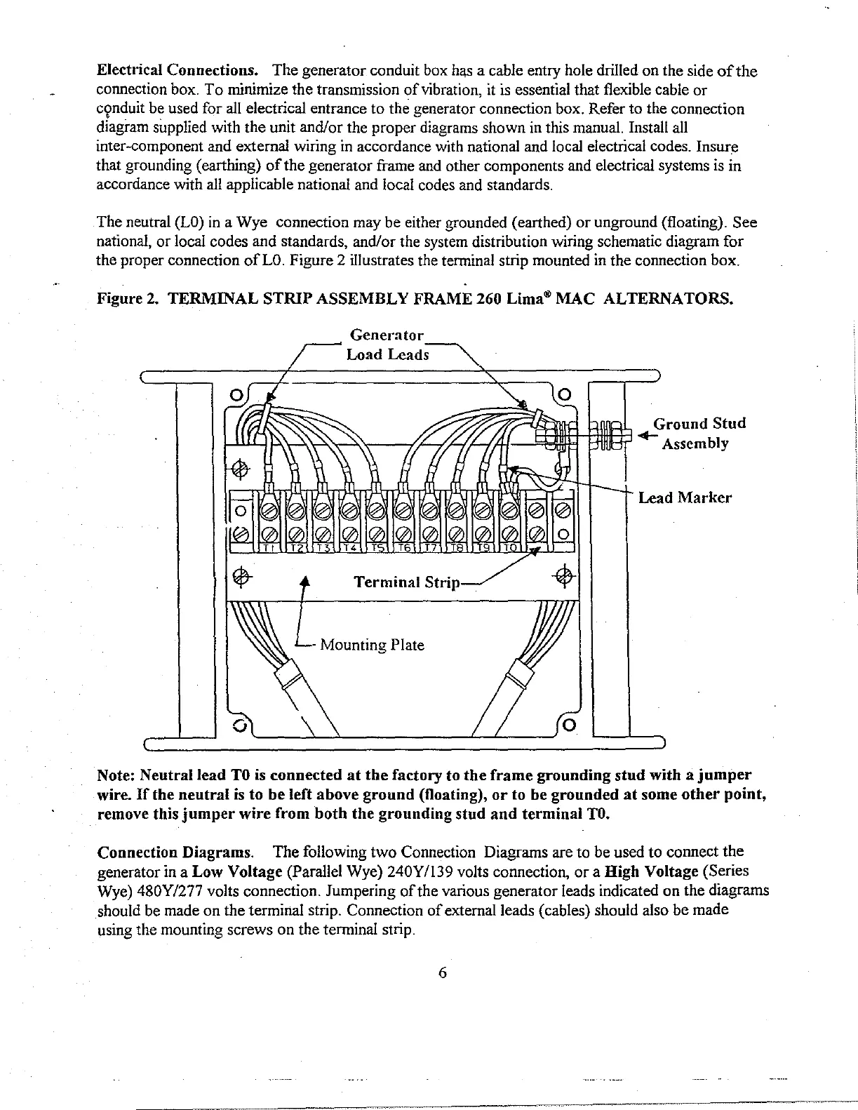
The neutral
(LO)
in
a Wye connection may be either grounded (earthed)
or
unground (floating). See
national,
or
local codes and standards, and/or the system distribution wiring schematic diagram for
the proper connection
of
LO.
Figure 2 illustrates the terminal strip mounted
in
the connection box.
Figure
2.
TERMINAL
STRIP
ASSEMBLY
FRAME 260 Lima"'
MAC
ALTERNATORS.
Generator
Load
Lead~
Terminal
Strip
- Mounting Plate
0
Ground
Stud
+-Assembly
Lead
Marker
Note: Neutral lead
TO
is
connected
at
the
factory to
the
frame
grounding
stud
with a
jumper
wire.
If
the
neutral
is
to
be
left
above
ground
(floating),
or
to be
grounded
at
some
other
point,
remove this
jumper
wire
from
both
the
grounding
stnd
and
terminal
TO.
Connection Diagrams. The following two Connection Diagrams are to be used to connect the
generator
in
a Low Voltage (Parallel Wye) 240Y/139 volts connection,
or
a High Voltage (Series
Wye)
480Y/277 volts connection. Jumpering
of
the various generator leads indicated on the diagrams
should be made on the terminal strip. Connection
of
external leads (cables) should also be made
using the mounting screws on the terminal strip.
6