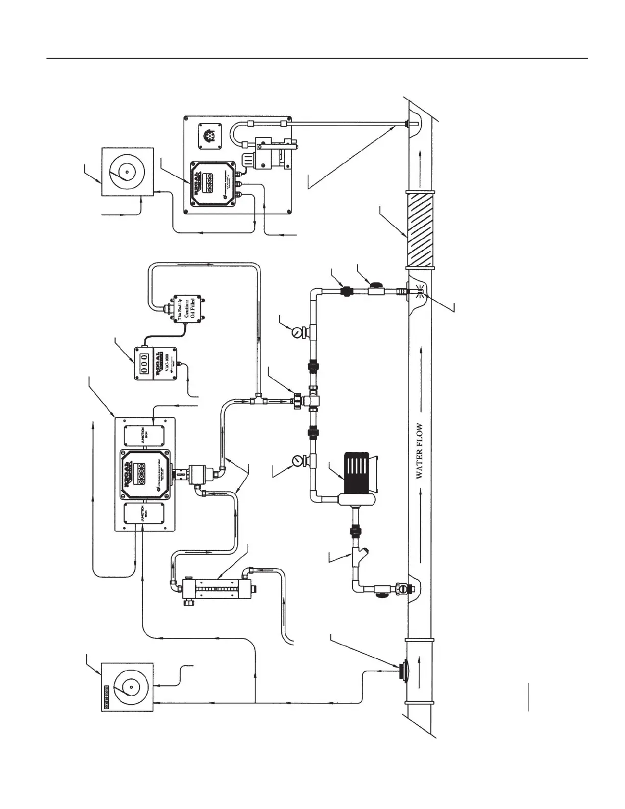
DRAWING NO. 1 — TYPICAL INSTALLATION
Flow Proportional Control System
Flow Recorder
(BY OTHERS)
4-20 Milliamp Analog Output Signal
Vacuum Tubing
GAS FLOW from
Vacuum Regulator
REGAL 7500
Remote Meter
Assembly
Isolation Valve (Typ.)
(BY OTHERS)
Booster Pump
(BY OTHERS)
REGAL Ejector
Assembly
Y-Strainer
(BY OTHERS)
Pipe Union (Typ.)
(BY OTHERS)
Gauge for
Supply
Pressure (Ps)
Gauge for
Back Pressure
(Pb)
REGAL Model
CRA-5000
Residual Analyzer
REGAL VAC-1000
Vacuum Monitor
Static Mixer
(BY OTHERS)
Chlorine Solution Injection into Center of Main Line
Residual
Sample Line
(BY OTHERS)
120/240 VAC
50/60 Hz
120/240 VAC
50/60 Hz
120/240 VAC
50/60 Hz
120/240 VAC
50/60 Hz
REGAL SMARTVALVE™
Model 7009
Residual Recorder
(BY OTHERS)
Water Flow Meter
(BY OTHERS)
Flow Analog Input Signal (4-20mA DC)
NOTE:
The sole purpose of this drawing is to show the gas flow path through the REGAL System components
and the order in which these components are connected.
19