User manual MR004DL/FA 07.03.02, Version 1.2 3
GmbH, Stettiner Str. 38, D-33106 Paderborn
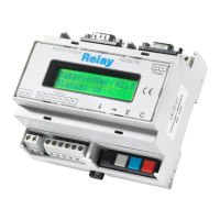
1 Installation and startup
Drill pattern:
Connectors:
RS232: GND Ground potential of the interface
TX Data line for reception (transmit of PC)
RX Data line for transmission (receive of PC)
RS485: S+, S- Terminals for RS-485 interface (observe polarity)
M-Bus: M+, M- M-Bus terminals (3 pairs). M-Bus devices are wired polarity
independent in parallel to the same line. The signs +, - mark only
the different bus lines.
Power: Earth for symmetry of bus and surge diverting
N, L Terminals for power supply (230V AC or 110VAC for –US version),
polarity independent
Power Slave Max Short
GND TX RX S+ S-
RS232 (PC) RS485
M-Bus
N L
PC
MODEM