Do you have a question about the RelFar FWH20-S10A and is the answer not in the manual?
Details the technical specifications including model, fiber interface, wavelength, power, focal length, adjustment ranges, and pressure.
Provides essential safety warnings for operation, emphasizing protective eyewear and keeping the product clean.
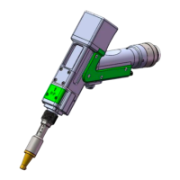
Illustrates the product's components with labels, including the galvanometer module, focusing module, and nozzle.
Explains how to connect the cooling water and auxiliary gas pipes, including requirements for gas and pipe connections.
Details the procedure for installing the optical fiber input, including alignment and locking the QBH module.
Shows the structure of optical lenses within the welding head, identifying collimating, focusing, and protective lenses.
Provides a detailed method for cleaning optical lenses using isopropyl alcohol and dust-free swabs.
Guides on how to disassemble and reassemble collimating, focusing, and protective lenses, emphasizing clean environment.
Presents dimensional drawings for the touch screen and mainboard for installation purposes.
Lists the electrical components required for the system, including motor wires, power boxes, and control cards.
Provides a comprehensive wiring diagram for the entire system, detailing connections between components.
Defines the 6-pin CN5 power supply interface for mainboard and galvanometer, specifying voltage and current.
Details the 8-pin CN1 interface for wire feeder connection, supporting motor and IO feeding methods.
Defines the 8-pin CN2 interface for laser connection, including modulation signals and status indicators.
Specifies the 4-pin CN3 interface for connecting a temperature sensor, detailing power and signal pins.
Defines the 4-pin HMI interface for power supply and communication with the mainboard.
Describes the 4-pin CN4 reserved serial port interface, noting it is not wired.
Defines the 4-pin CN6 interface for external start buttons and safety interlocks.
Details the 6-pin CN7 interface for general inputs, including water chiller alarm and reserved inputs.
Specifies the 6-pin CN8 interface for general outputs, suitable for driving relays.
Defines the 4-pin CN9 interface for general inputs, including low pressure alarm.
Mentions the provision of two DB9 galvanometer interfaces, male and female.
Introduces the 7-inch TFT touch screen HMI, its features, and real-time display capabilities.
Covers setting parameters for homepage, welding mode, power, frequency, duty cycle, swing, and wire feeding.
Details system parameters like pulse times, rise/fall times, gas delays, and language settings.
Explains parameters for wire feeding, including withdrawal speed, supplement speed, and continuous feeding.
Provides a section for monitoring the current system's Input/Output (IO) status.
Covers device-specific parameters like laser rated power, galvanometer angle, and wire feeding direction.
Guides on setting the protective lens temperature alarm limit and enabling the alarm.
| Model | FWH20-S10A |
|---|---|
| Brand | RelFar |
| Category | Welding Accessories |
| Type | Welding Helmet |
| Lens Shade | DIN 9-13 |
| Power Source | Solar + Lithium Battery |