4.
Inspection and Maintenance
Refer to Figures 1 & 2.
1. Review the latest NFPA 13 and NFPA 25 Standards,
any appropriate dry pipe or deluge valve installation
bulletins, and the section in this bulletin titled “Instal-
lation” to ensure that the pressure maintenance de-
vice is installed properly.
2. Make sure that both ¼” globe valves (Item 4) are
open and that the ¾” ball valve (Item 5) is closed.
3. Check the gas pressure in the dry pipe, deluge or
preaction system at the pressure gauge located on
those devices. See the section titled “Adjustment” if
any are required.
4. If maintenance is to be performed on Items 1, 2 or
3 of the pressure maintenance device, make sure
that both globe valves (Item 4) are closed and that
pressure has been relieved from the section through
the ¼” union (Item 6). These valves must be opened
again in order to restore proper automatic operation.
5. The strainer (Item 2) should be cleaned periodically
to prevent contamination from blocking air flow. This
can be done by removing the strainer’s cap and wip-
ing or blowing off any collected debris.
6. Make sure the check valve (Item 3) is installed ac-
cording to the schematic with the arrow on its hex-
agonal side pointing in the required direction of air
flow.
7. If the regulator (Item 1) in the Model A-2 Pressure
Maintenance Device is constantly leaking at the ad-
justing screw, the regulator may contain dirt keep-
ing the poppet open and should be cleaned or re-
placed.
8. Check the inside housing of pressure switch (Item
1) of the Model B-1 Pressure Maintenance Device
for dirt or foreign matter and verify that the wiring is
fastened securely and is wiring insulation is in good
condition.
WARNING: Do not contact the electrical wiring
when the power is on
Installation
As shown in Figures 4 through 13, Pressure Maintenance
Devices are installed in the air supply line leading to the dry
pipe valve, deluge or preaction systems. With the Model
A-2 PMD the air supply is a tank mounted compressor with
a pressure control switch, or a Nitrogen supply equipped
with a regulating device. With the Model B-1 PMD, the
air supply is an air compressor without a pressure control
switch. An extra outlet connection is provided on all of the
models for mounting an optional pressure gauge to moni-
tor the outlet pressure.
• Model A-2 Pressure Maintenance Device
a. Make sure the air flow through the Pressure
Maintenance Device is as shown by the arrows
in Figures 1, 4, 6, 8, 9 and 11-13.
b. Install the Pressure Maintenance Device as close
to the dry pipe valve air line trimmings as pos-
sible. Install the Pressure Maintenance Device
in the air supply immediately leading to the del-
uge or preaction trim. Refer to separate dry pipe
valve, deluge valve or preaction system bulletins
for the additional installation information.
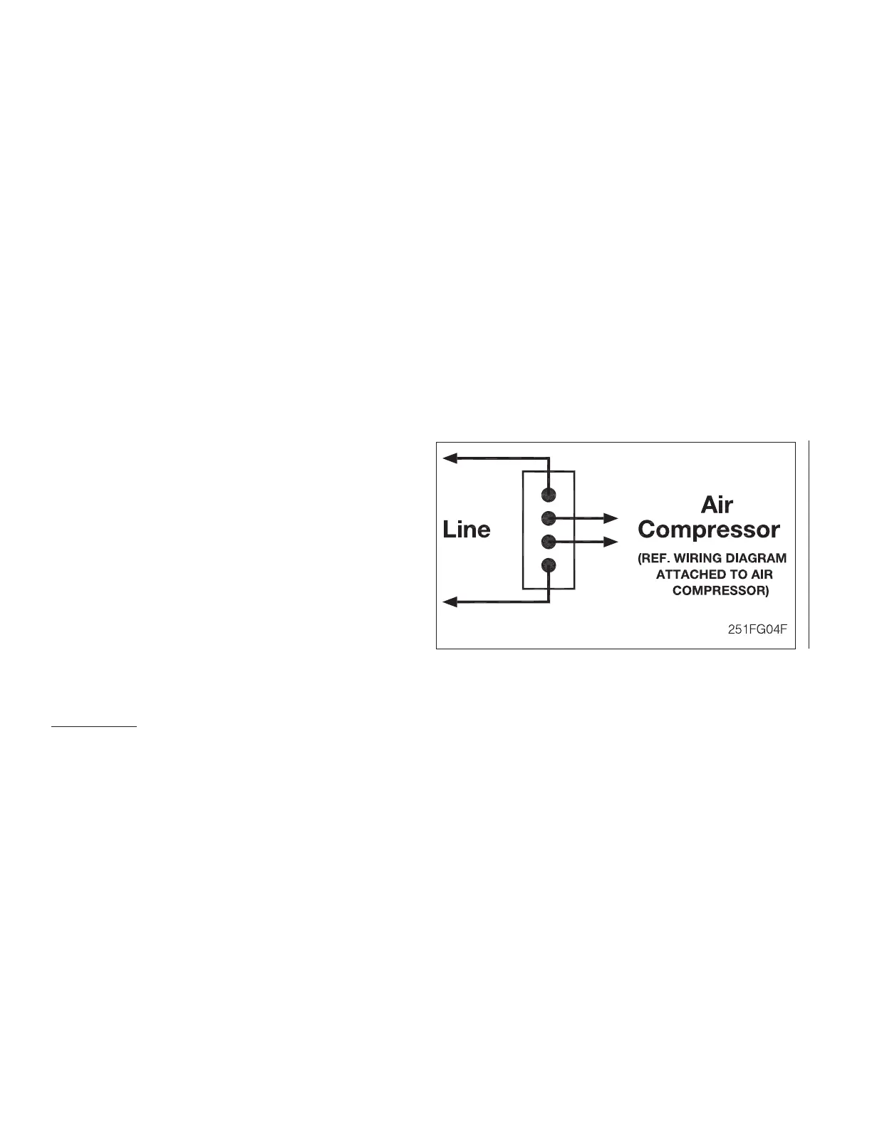
• Model B-1 Pressure Maintenance Device
a. Make sure the air flow through the Device is as
shown by the arrows in Figures 2, 5-7 and10.
b. Remove the pressure switch’s (Item 1) cover and
connect the wiring in accordance with the Nation-
al Electric Code or other appropriate standards.
The connections should be as shown in Figure
3 for single phase wiring of thermally protected
compressor motors. Refer to separate dry pipe
valve and deluge valve bulletins for additional in-
stallation information.
c. For 3-phase wiring, a listed and/or approved,
properly sized magnetic motor starter with ap-
propriate NEMA enclosure must be provided.
The wiring of the pressure switch, motor starter,
and air compressor must be in accordance with
the National Electrical Code, or other appropri-
ate standards.
Figure 3
 Loading...