9.
System Requirements
NFPA (National Fire Protection Association) 13 titled “In-
stallation of Sprinkler Systems”, specifies that Accelera-
tors (quick-opening devices) are required in dry systems
having capacities of more than 500 gallons. However, ex-
ceptions permit the omission of quick-opening devices for
larger systems when water can be delivered to the inspec-
tor’s test connection in less than 60 seconds.
• Reliable’s Accelerator is UL Listed for system volumes to
1500 gallons. This capability is also approved by FM.
• System pneumatic pressure must be maintained at a
minimum of 15 psi in order for the Accelerator to be
effective.
It must be cautioned that accelerator operation and water
delivery at the inspectors test connection does not occur
at the same time. There is a delay while the air is being
expelled through the inspectors test connection ahead of
the water. This time delay depends on the piping configu-
ration system size, available water supply and other factors
which are beyond the control of the accelerator and restrict
the system’s capability to deliver water in the 60 second
time requirement. While field installation experience will
aid in the determination of system size limitations, it is rec-
ommended that the Reliable Technical Service Department
be consulted when large volume systems are encountered.
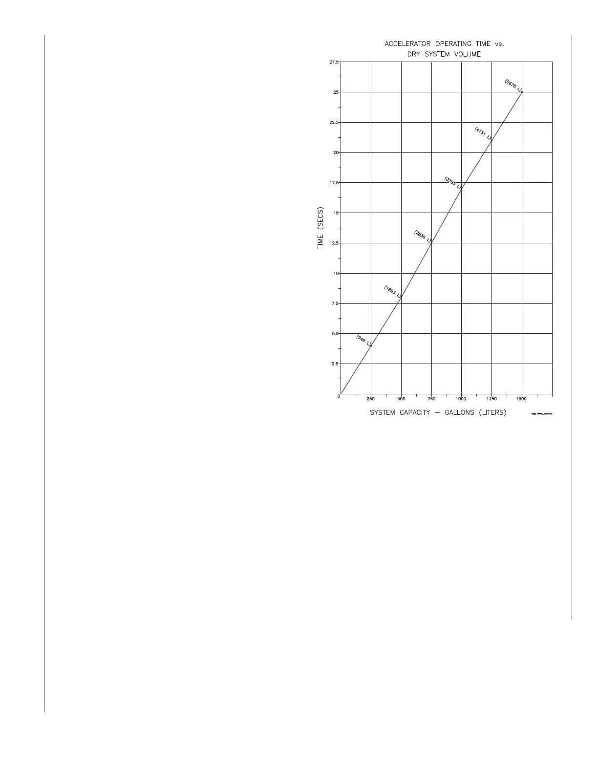
Figure 7 provides an approximate graph of actual Accel-
erator operating time versus system size when one sprin-
kler head opens. The time of operation of the Accelera-
tor is relatively unaffected by inlet pressures so the graph
applies for all normal dry system pressures from 25 psi to
50 psi (1.7 bar to 3.4 bar). As described in the following
section, water delivery time will significantly exceed the ac-
celerator operating times shown is Figure 7.
Resetting Procedure For Model D Dry Pipe
Valve Systems (Refer to Figs. 1 & 2)
1. Isolate the Accelerator by closing the valves A and
C, Fig.
2. Close the air and water supply valves to the dry pipe
valve. Drain and fully reset the dry pipe valve in ac-
cordance with its technical bulletin.
3. Re-close the main water supply control valve and
then re-open the dry pipe valve’s drain valve.
4. Remove Plugs B and E, Fig. 2.
5. Remove the body drain plug from the lower section
of the Accelerator, Item #3, Fig 1.
6. Remove the top chamber drain plug, Item #3, Fig.
1, from the side of the Accelerator. If water is pres-
ent in the top chamber, disassemble the Accelerator,
and clean and dry the top and middle chambers and
diaphragm assembly using a clean lint free cloth. Re-
assemble the Accelerator. Replace the top chamber
drain plug using new thread sealant.
7. Remove the Accelo–Check Body, Item #19, Fig. 1,
and gently lift the Accelo–Check Diaphragm Assem-
bly, Item #22, Fig. 1, to verify venting of the middle
chamber. Carefully reinstall these parts.
8. Partially open Valve A, Fig. 2, gently purging any
water which may be in the trim lines. Close Valve A.
Re- place Plugs B and E, Fig. 2. Partially open Valve
A and gently purge. Close Valve A and replace the
body drain plug at the lower section of the Accelera-
tor, Item #3, Fig. 1.
9. Pressurize the Accelerator by opening Valve A, Fig.
2. Open Valve C and check for leakage at the Ball
Drip Valve D, Fig. 2. The top chamber pressure of the
Accelerator should equal the system pressure.
10. Slightly open the main water supply control valve.
Close the main drain valve when water flows, then
fully open the main supply valve. The system is now
ready for service.
Fig. 7
 Loading...