4
Living Room
Outlets
(200+ Watts)
Before you begin installing your Reliance Controls transfer switch system, you need to create a plan for the appliances you choose
to run during a power outage. To do this, it’s helpful to first know how your generator produces power. If your generator has four-prong
locking 20 or 30 Amp output receptacles, and is set-up for home stand-by operation, it likely will produce 120/240 Volt power, or power
similar to your electrical utility. This type of power generation is useful as it: 1) allows common 120 Volt circuits, such as lights or small
appliances, to be operated, and 2) allows two 120 Volt circuits to be linked together to operate a 240 Volt device, such as a well pump.
Because of the way in which larger portable generators are designed, they generate power in two equal halves. A generator which
has output of 5000 continuous running watts, for example, generates power from two 2500 watt “sides”. In setting up a transfer switch
to get the most power from your generator, it is desirable to “balance the load” between the two phases (sides) of your transfer switch.
Devices which will consume the most of the generator’s wattage should be divided between the two phases. A load balancing example is
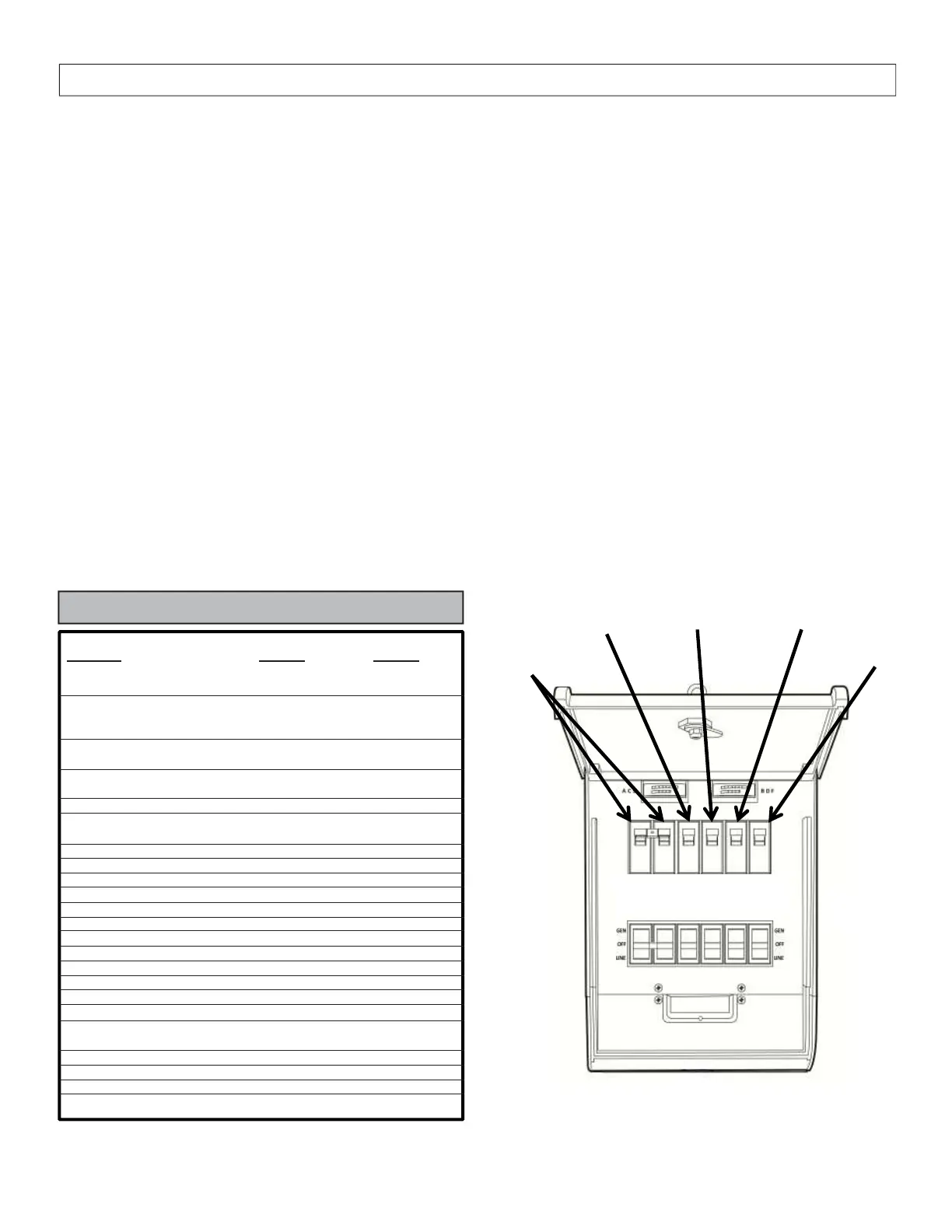
shown in Figure 1. *Only a 240v circuit is already balanced.
For example, consider wiring the house breaker controlling the sump pump to toggle switch C, the refrigerator breaker to toggle switch D,
the furnace to switch E, and the breaker controlling your living room outlets to switch F. You may want to reserve switches A and B to be
linked with a handle tie and wired to a double pole breaker controlling, for example, a 240 volt circuit such as a water heater or well pump.
The Residential Wattage Requirements Table below shows sample wattages used by typical household appliances and can help
you plan the setup of your transfer switch. Use the running watts of your appliances rather than starting watts when dividing them
between the two halves of the transfer switch. Check your appliances for actual wattage ratings if possible.
Your Reliance Controls transfer switch allows you to manage the load on your generator manually by switching appliances on and
off as you need them, so the capacity of either half of your generator is not exceeded. However, if you prefer not to manage your
transfer switch loads manually, leave a buffer equal to the largest start-up wattage requirement of all of the appliances you are going to
run continually when doing your calculation. This buffer, along with the peak wattage of your generator, will allow for the periodic motor
start-up of any one large appliance, such as your refrigerator. You can visually monitor the amount of wattage being used by the
appliances your generator is powering at any time by viewing the watt meters (if included) near the top of the transfer switch.
PRE-INSTALLATION PLANNING OF THE GENERATOR LOAD
TYPICAL RESIDENTIAL WATTAGE REQUIREMENTS
Running Add Start-Up
Appliance Wattage Wattage
Furnace (1/3 HP) 700 1,400
Window Air Conditioner
6000 BTU 1,200 2,100
Well Pump (1/3 HP) 750 1,400
Well Pump (1/2 HP) 1,000 2,350
Sump Pump (1/3 HP) 800 1,300
Garage Door Opener (1/4 HP) 550 1,100
Garage Door Opener (1/3 HP) 750 1,400
Clothes Dryer (Gas) 700 1,800
Dishwasher (Cool Dry) 700 1,400
Dishwasher (Hot Dry) 1,450 1,400
Vacuum Cleaner 1,000
0
Hair Dryer Check Dryer Check Dryer
Circular Saw 800 2,000
Well Pump
(1,000 Watts)
Sump Pump
(1,050 Watts)
Refrigerator
(800 Watts)
Furnace
(875 Watts)
Figure 1
A B C D E F
Left Meter = A, C, E Right Meter = B, D, F
 Loading...