page 14 of 25 GBB-EXKOM-08157/3
The output status will be shown through yellow LED’s as follows:
Output #1 Control Valve QV#1 Active = LED on
Output #2 Control Valve QV#1 Active = LED on
Output #3 Air Valve QV#1 Active = LED on
Output #4 Air Valve QV#1 Active = LED on
Output #5 alarm-relay #1 Save status = LED on
Output #6 Control Valve QV#2 Active = LED on
Output #7 Control Valve QV#2 Active = LED on
Output #8 Air Valve QV#2 Active = LED on
Output #9 Air Valve QV#2 Active = LED on
Output #10 alarm-relay #2 Save status = LED on
Output #11 summary alarm-relay Save status = LED on
Unlisted In-/Outputs are not used.
Terminal 1 and 2 for the connection of the power supply voltage of in- and output are
at the junction block X1 and X2:
Terminal#1: GND
Terminal#2: +24VDC
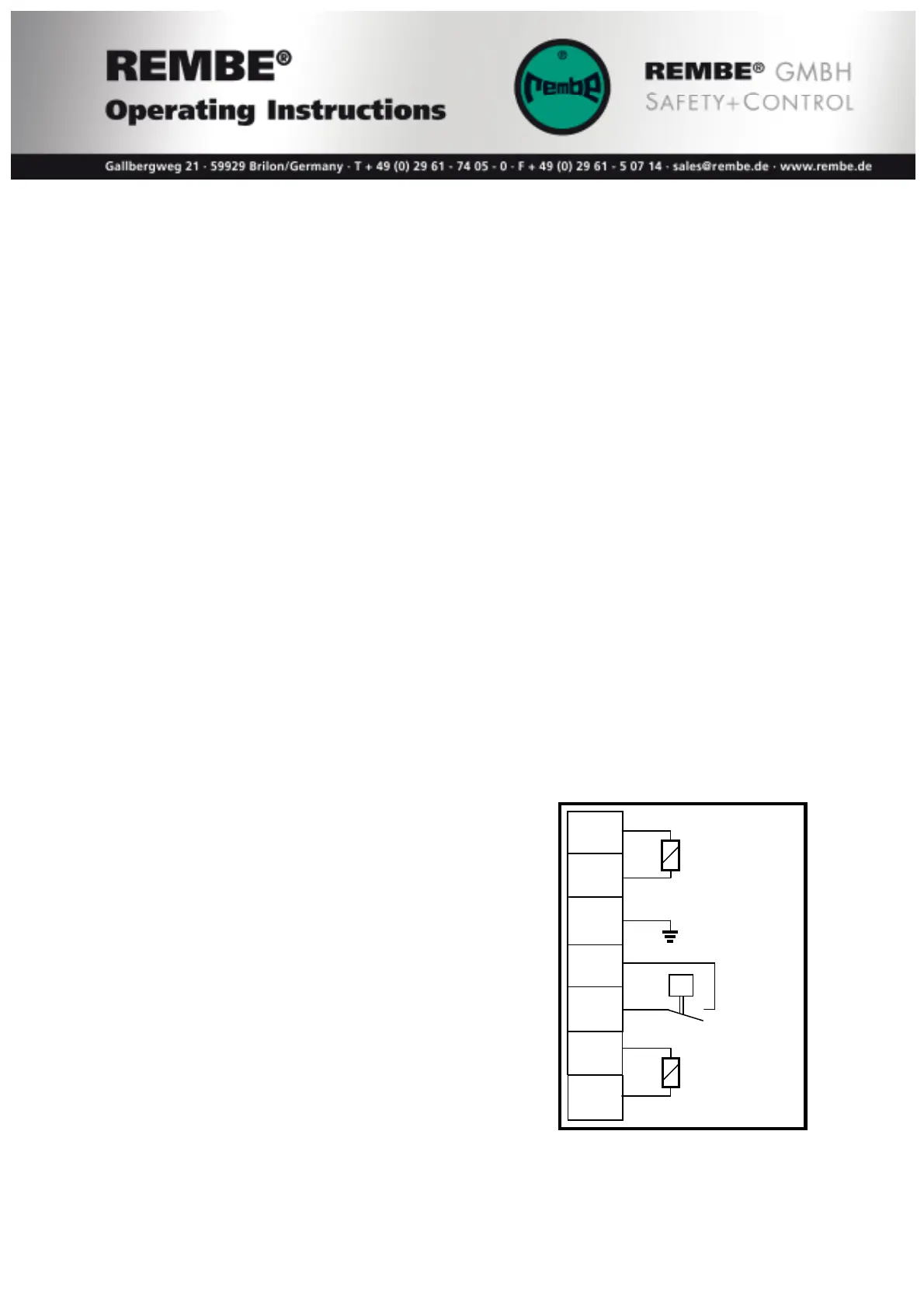
4.3.2. Output modules QV II Quench Valve - wiring
In case of alarm or all other failure the output modules QV II Quench Valve is
activated by the CPU and isolates the pipe by means closing the QV II Quench Valve.
During normal mode the solenoid valve
of QV II Quench Valve are powered by
the EXKOP
®MINI
Safety Controller.
Also the pressure switch is controlled
by the CPU.
The terminals in the CPU of the EXKOP
®MINI
Safety Controller will be connected to
the terminals of the QV II Quench Valve
acc. following wiring diagram.
Recommend cable:
Shielded cable with cross section of 1mm
2
.
1
Valve
2 Air in
V1
PE
P Pressure
4 switch
5
Valve
6 Air out
V2