page 13 of 25 GBB-EXKOM-08157/3
4.3.1 EXKOP
®MINI
Safety Controller – operation and wiring
The EXKOP
®
Safety Controller controls the connected input and output modules
automatically. A manual handling is only necessary during the initiation and test run.
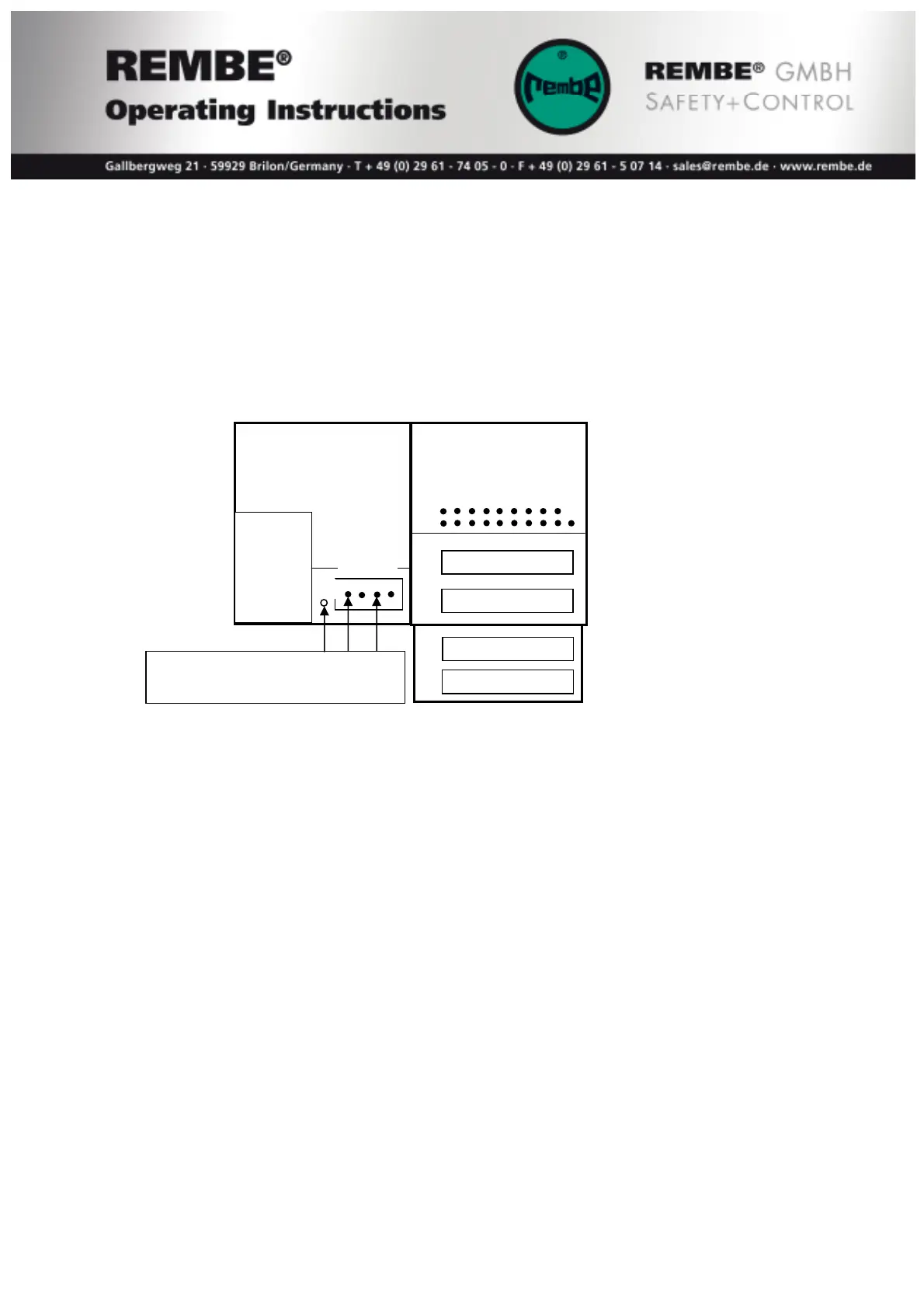
The power supply of the EXKOP
®MINI
Safety Controller must be connected to a 4-pole
terminal of the CPU-Modules at the clamp + and – with 24V direct voltage.
terminals for
- Inputs
- Outputs
+24VDC
GND
Function of LED’s on the CPU-Module DM 465
The yellow LED U indicates the power supply of in and outputs. Below a power
supply of approx. 18VDC the LED turns dark.
Note: The control modules have 16 Inputs with green LED’s and 16 Outputs with
yellow LED’s. But it will be only shown 8 In-/Outputs at the same time. Press the little
white Key at the modules to switch between:
Yellow LED S#… In-/Output 1 – 8
Yellow LED S#+1… In-/Output 9 – 16
The input status will be shown through green LED’s as follows:
Input #1 Bursting disc #1 Save status = LED on
Input #2 Pressure air QV II #1 Save status = LED on
Input #3 Bursting disc #2 Save status = LED on
Input #4 Pressure air QV II #2 Save status = LED on
Input #5 Reset key pressed = LED on
Input #14 Bypass C Jumper installed = LED on
Input #15 Bypass B Jumper installed = LED on
Input #16 Bypass A Jumper installed = LED on
24VDC
connection voltage: 24VDC
max. capacity 100W
PE
CPU 470 DM465
X1
X4
X5
X2