page 17 of 25 GBB-EXKOM-08157/3
I
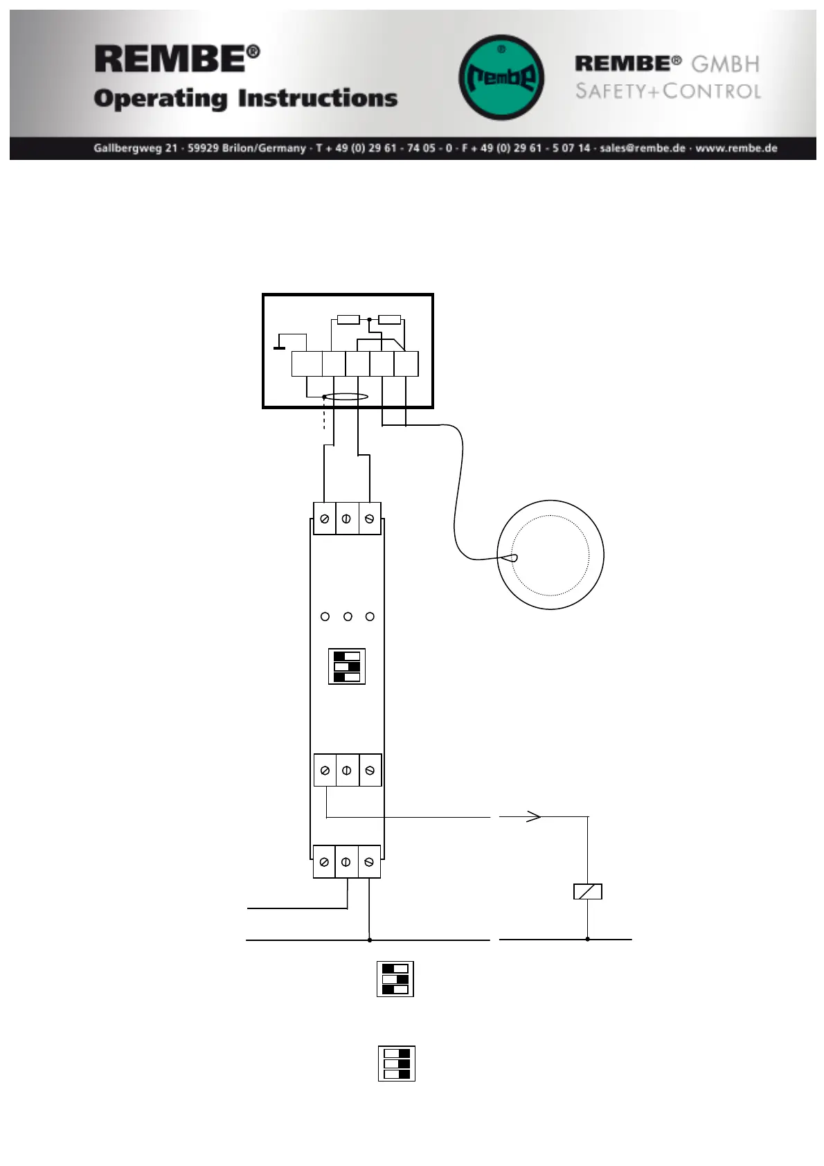
S1: output 7 blocked
S2: output. 9 parallel output 7
S3: input w. LB/SC supervision
II
S1: output 7 inverted
S2: LB/SC Supervision
S3: input without LB/SC
The input of the KFD2-ST2-Ex1.LB electronic has to be connected to the terminals
#1 and #2 in the junction box and in the EXKOP
®MINI
Safety Controller at the
terminals according to the terminal diagram. The signaling unit of the bursting disc or
the Q-Rohr
®
has to be connected to the terminals #3 and #4 in the junction box.
500Ω 10kΩ
1 2 3
yel red green
Bursting disc, …
I II
S1
S2
S3
7 8 9
output 7 signal
13 14 15
20 – 30 VDC L+ CPU input
M- M-
Position of switches as standard:
I II
S1
S2
S3
In case the module is not in use the switches have to be in the following position:
I II
S1
S2
S3