page 20 of 25 GBB-EXKOM-08157/3
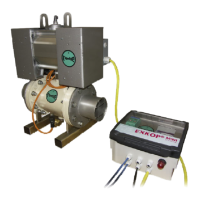
Installation Instructions for QV II Quench Valve
Preparation of installation place
The pipe work has to be fitted with counter flanges
according to the mounting and installation
instructions.
Mounting of the QV II Quench Valves
Be sure to allow the counter flanges to cool after welding.
This is to ensure that the rubber Quench seal is not
damaged by heat during the mounting process.
The electronic supply needs to be cut.
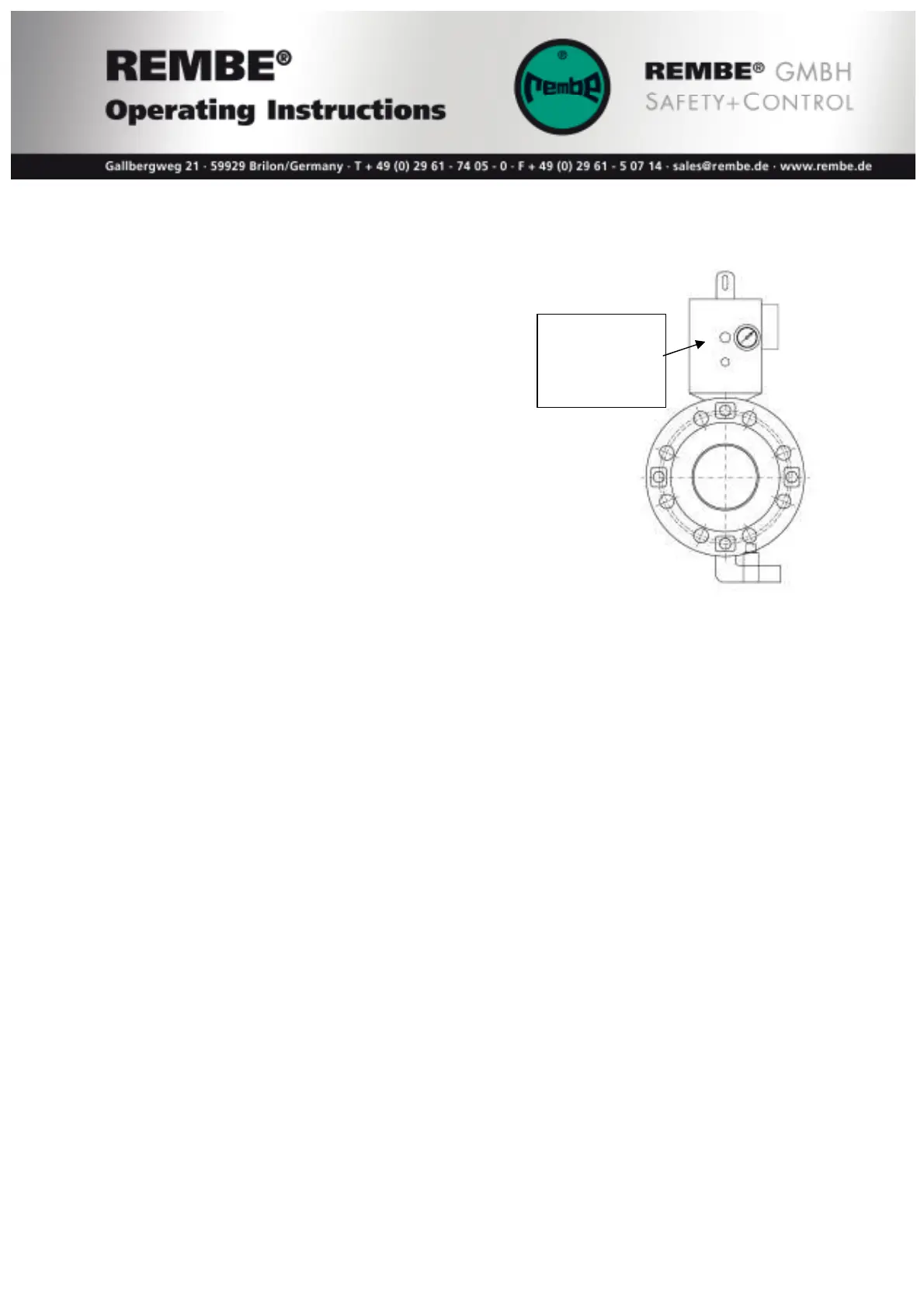
For better inspection the gauge should be easily viewed once the valve is mounted.
The air supply has to be connected to the pressure reducer (1/4“-connecting).
Mounting QV II-3 to QV II-10
The bolt flanges of the QV II Quench Valves have to be tightened to following
specifications:
bolts M 16 80...100 Nm
bolts M 20 80...120 Nm
The screws must be tightened cross over. Torque each bolt in sequence to 80 Nm and
than 2 times again to 100 (120) Nm. After the first operating cycles the torque has to
be checked. Minimum one check per year shall be made and this inspection must be
documented.
Now the electrical wiring of the QV II Quench Valve can be connected.
Pressure
reducing valve
(preset)
manometer