Do you have a question about the RenewAire RH Series and is the answer not in the manual?
Details risks associated with high voltage, arc flash, and required safety precautions.
Cautionary notes on disconnecting power and preventing accidental reconnection.
Warning about high temperatures produced by the device and the need for PPE.
Emphasizes following best practices, codes, and authorized personnel for installation.
Instructions for recording heater type, model, and serial number for factory assistance.
Description and location of the typical unit label found on the appliance.
Overview of heater types, typical kW range, voltages, control voltage, and standard features.
Detailed table of duct sizes, kW, voltage, dimensions, and weight.
Chart showing required minimum airflow for different heater capacities (kW).
Formulas for calculating minimum airflow and air velocity based on heater capacity.
Formula to calculate line current based on watts and line voltage.
Formulas for determining kW required for temperature rise and calculating temperature rise.
Details on RH-D/RH-W heaters, their open-coil design, and suitability for various applications.
Explanation of low airflow shut-off, auto-reset, and manual reset thermal cutouts.
Guidance on airflow direction for RH-D units and temperature sensor placement.
Information on airflow direction for RH-W units, which can be bidirectional.
Overview of available duct sizes, wattages, and control methods for RH-D and RH-W heaters.
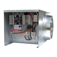
Detailed description of RH-D components including airflow sensor and thermal cutouts.
Details of RH-W components, airflow sensor, thermal cutouts, and SSR.
Explanation of the CTH291 thermostat's dual mode operation and features for RH-W heaters.
Detailed drawings showing dimensions for RH-D/RH-W units with 6-inch duct collars.
Detailed drawings showing dimensions for RH-D/RH-W units with 8-inch duct collars.
Detailed drawings showing dimensions for RH-D/RH-W units with 10-inch duct collars.
Detailed drawings showing dimensions for RH-D/RH-W units with 12-inch duct collars.
Wiring diagram for RH-D heaters operating on 120 VAC.
Wiring diagram for RH-D heaters at 208/240 VAC, 1-6 kW.
Wiring diagram for RH-D heaters at 240 VAC, 8-11.5 kW.
Wiring diagram for RH-W heaters operating on 120 VAC.
Wiring diagram for RH-W heaters at 208/240 VAC, 1-6 kW.
Wiring diagram for RH-W heaters at 240 VAC, 8-11.5 kW.
Table detailing unit weights based on duct collar diameter and kW capacity.
Requirements for minimum airflow and ideal installation location to prevent heat loss.
Guidelines for unit orientation and required clearances to combustible surfaces.
Recommendations for ductwork connections, materials, and insulation.
Instructions for checking and repositioning the temperature sensor for correct airflow direction.
Procedure for connecting the high voltage electric service to the unit.
Instructions for connecting the external 0-10 VDC thermostat to the RH-W heater.
Steps for mounting the RH-W thermostat base plate and housing.
Details on thermostat wiring terminals and setting DIP switches for desired operation.
Explanation of Comfort and Economy modes, including override and sensor inputs.
Procedure for bringing low voltage wiring into the unit through factory knockouts.
Guidance on setting the potentiometer for desired output temperature on RH-D heaters.
Information on required annual maintenance checks for RH-D and RH-W heaters.
Steps to test the Airflow Sensor (AFS) and Duct Sensor (DS) on RH-D controllers.
Procedure for testing the D21-TSSR control module, including power and sensor inputs.
Tests for heating elements and transformer on RH-D units to diagnose issues.
Steps for testing the CTH291 thermostat and reviewing dip switch settings for RH-W.
Procedure to test the Airflow Sensor (AFS) on RH-W models.
Tests for the D21-PSSR control module and Solid State Relays (SSR) on RH-W units.
Tests for heating elements and transformer on RH-W units.
Description of how RH-D heaters maintain outlet air temperature via SSR control.
Explanation of RH-W heater operation controlled by a 0-10 VDC signal from a thermostat.
Information on how to contact RenewAire customer service for assistance with RH Electric Duct Heaters.
List of service parts for RH-D heaters with 1-6 kW capacity, categorized by layout.
List of service parts for RH-D heaters with 8-11.5 kW capacity, including specific components.
List of service parts for RH-W heaters with 1-6 kW capacity, categorized by layout.
List of service parts for RH-W heaters with 8-11.5 kW capacity.
Information about RenewAire's history, IAQ enhancement, ERVs, and sustainable manufacturing practices.