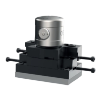
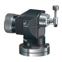
The Renishaw NC4+ Blue is a laser-based non-contact tool setting system designed for high-speed and high-precision measurement of cutting tools on machining centers under normal operating conditions. It is suitable for use on vertical and horizontal machining centers, multi-tasking machines, and gantry machining centers.
Function Description
The NC4+ Blue system provides non-contact tool setting, which involves moving a tool through a laser beam. When the beam is broken, the system detects the presence of the tool and transmits output signals to the controller, allowing for the establishment of tool dimensions (tool measurement) or detection of broken tools. The system is designed to operate with minimal maintenance as a permanent fixture in challenging machining environments.
Important Technical Specifications
- Principal application: High-precision, high-speed non-contact tool setting and tool breakage detection on all sizes of vertical and horizontal machining centers, multi-tasking machines, and gantry machining centers.
- Transmission type: Hard-wired connection.
- Repeatability: F115 and F145 models offer ±0.5 μm (19.69 μin) 2σ; F230 and F300 models offer ±0.75 μm (29.53 μin) 2σ.
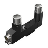
- Output signal (from interface unit): Two voltage-free, solid-state relays (SSR). Each can be either normally open or normally closed (selectable via switch). Current (maximum) 50 mA, voltage (maximum) ±50 V. The interface contains an auxiliary relay which can be used for switching the output between the NC4+ Blue and a spindle probe. This relay can also be used to control an air blast solenoid (optional).
- Supply voltage (to interface): 11 Vdc to 30 Vdc.
- Supply current (to interface): 120 mA @ 12 Vdc, 70 mA @ 24 Vdc.
- Supply protection: Resettable fuses in interface. Reset by removing power and cause of fault.
- Electrical connection arrangement: Systems with connector: Connector socket. Hard-wired systems: Cable on the end of the unit. Other configurations are available on request.
- Cable (to interface): Specification: Ø6.0 mm (0.24 in), two twisted pairs, two individual cores plus screen, each core 18 x 0.1 mm insulated. Length: 12.5 m (41.01 ft).
- Electrical connection: Systems with connector: cable with bayonet-type plug, connector socket on the end of the unit. Hard-wired systems: cable on the end of the unit. Other configurations are available on request.
- Barrier air pneumatic supply: Air supply to the NC4+ Blue unit must conform to BS ISO 8573-1 Class 1.4.2. 6.0 bar (87.02 psi) maximum. Systems with connector: Ø4.0 mm (0.16 in) x 5.0 m (16.40 ft). Hard-wired systems: Ø3.0 mm (0.12 in) x 5.0 m (16.40 ft).
- Air blast pneumatic supply: Air supply to the air blast must conform to BS ISO 8573-1 Class 2.9.4. Ø6.0 mm (0.24 in) x 5.0 m (16.40 ft), 6.0 bar (87.02 psi) maximum.
- Laser type: Class 2 laser product. 1 mW maximum output emitted wavelength 405 nm.
- Laser beam alignment: The unit is supplied with an adjustable mounting plate on the underside.
- Weight (including cable): 1080 g (2.38 lb) to 2000 g (4.4 lb) depending on configuration.
- Mounting: M4 (x 3), M10 (3/8 in) or M12 (1/2 in) bolts (not supplied) for mounting via adjuster plate. Other fixing arrangements are available on request.
- IP rating: IPX6 and IPX8, BS EN 60529:1992+A2:2013.
- Storage temperature: -25 °C to +70 °C (-13 °F to +158 °F).
- Operating temperature: +5 °C to +55 °C (+41 °F to +131 °F).
- Minimum tool diameter or feature size: F115: 0.03 mm (0.001 in); F145: 0.05 mm (0.002 in); F230: 0.1 mm (0.004 in); F300: 0.2 mm (0.008 in).
Usage Features
- Installation: The system requires installation of an air preparation pack, the NC4+ Blue unit, and an NCi-6 interface unit. Electrical power must be supplied, and barrier air pressure set. The unit needs to be aligned to the machine axes and then calibrated using appropriate software.
- Air Supply: A continuous regulated air supply of up to 0.6 MPa (87.02 psi) is required for the barrier air, conforming to BS ISO 8573-1 Class 1.4.2 and being moisture-free. The air blast also requires an air supply up to 0.6 MPa (87.02 psi), conforming to BS ISO 8573-1 Class 2.9.4, controlled by a solenoid valve.
- PassiveSeal™: In case of air supply failure, a PassiveSeal™ inside each NC4+ Blue unit activates to protect the unit from contaminants, causing it to enter a trigger state where the laser beam will not be emitted.
- Alignment: The NC4+ Blue unit must be aligned so that the laser beam is parallel/perpendicular to the machine's axes within recommended tolerances. This is achieved using a beam alignment macro and adjusting X, Y, and Z axes. For best performance, Renishaw recommends using a ball-nosed cylinder-type calibration tool. A mobile app (NC4+ Blue app) is available for step-by-step alignment instructions.
- Software: Macro programming software is available for tool setting routines. Renishaw provides "Probe software for machine tools – programs and features" data sheet and programming guides for various machine tool controller types. Mobile apps (NC4 app, GoProbe app) are available for configuration, maintenance, and troubleshooting.
- NC4 Set-up Tool (A-4114-8000): This battery-operated device provides a visual indication of signal strength at the receiver head via a numerical display, aiding in alignment. It requires a 1/2 AA size 3.6 V Lithium-thionyl chloride battery, offering approximately 700 hours of continuous operation.
Maintenance Features
- Minimal Maintenance: The NC4+ Blue unit is designed for minimal maintenance as a permanent fixture in machining environments.
- Filter Element Replacement: Air preparation filter elements should be regularly inspected and replaced when dirty or wet, at least once a year. This involves unscrewing filter bowls, removing O-rings, and fitting new elements and O-rings.
- Membrane Dryer Module Replacement: The membrane dryer module should be replaced based on the dew point indicator (B) status or at least once every four years. Indications for replacement include yellow (water flow into drier) or brown/black (membrane contaminated/oil carryover) dew point indicator.
- Optics Cleaning: The optics should be cleaned by trained personnel. This involves switching off electrical power, removing the air supply, unscrewing the access panel from the transmitter head, inspecting for debris, inserting a cleaning tool, purging air, spraying solvent cleaner through a nozzle tube onto the lens, wiping with a swab, and then spraying clean air to remove solvent traces. The MicroHole in the access panel should also be cleaned.
- Air Blast Nozzle Replacement: The air blast nozzle can be replaced if damaged. This involves switching off electrical power, removing air supply, isolating air blast supply, unscrewing the old nozzle, and fitting a new one.
- Head Alignment: If transmitter and receiver heads are suspected to be misaligned, a head alignment procedure can be performed using a voltmeter or the NC4 set-up tool to maximize the signal strength at the receiver head. This involves adjusting pitch and rotation locking screws on the transmitter head.
- Fault-finding: A comprehensive fault-finding guide is provided, covering symptoms like failure to turn on, no laser beam, poor repeatability, voltage outside range, flashing status LED, and dirty lens/blocked air hole, along with their causes and recommended actions.