Thyristor control units for use with vibratory feeder units
The REOVIB 514 range of control units are suitable for powering vibratory feeders which have a mechanical vibrating frequency
which the same as, or double that of mains frequency. The adjustment of feeder throughput is achieved by using a triac with
phase angle control. The set point for the feeder throughput can be derived from a potentiometer, a signal voltage 0…10 V or a
signal current 0/4…20 mA. The set point input is isolated from live mains. The set point range can be adjusted to suit the
feeder unit by using trimmers “Umin “ / “Umax” (see “effects of trimmers Umin / Umax”).
The units can operate with feeders which have a mechanical vibrating frequency of 50 Hz or 100 Hz, ie 3000/6000 vibs/min (for
60Hz mains supply this would be 60 Hz or 100 Hz, ie 3600/7200 vibs/min). The mechanical frequency is determined, externally,
by the use of a link between terminals 19 and 20; without link = 50 Hz or 3000 vibs/min and with link = 100 Hz or 6000 vibs/min.
An enable input is provided on terminals 8, 9 and 10 for power free switching of the output (eg from a PLC). This input can be
operated from external contacts or with a signal voltage 12...24 V. The unit is enabled when the contacts are closed or when a
signal voltage is applied. The enable input is isolated from the mains. An additional control input is provided on terminals 1 and
2 for use with other control units, such as a track controller. When these inputs are not used, then each pair of terminals 1and
2, as well as 8 and 9 must be linked.
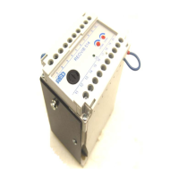
The unit is supplied in a simple to install modular housing which is suitable for both DIN rail mounting (EN 50022-35) and back
panel mounting. The terminals have safety covers, according to VBG 4 standards.
Technical data
Type REOVIB 514 51401
Supply voltage 230 V, + 6 % / - 10 %, 50/60 Hz
Output voltage 0…210 V
Output current 0.5…6 A
Set point source
Potentiometer 10 kΩ
0…10 V, DC Ri 20 kΩ
0…20 mA Ri 500 Ω
Enable input
Contact / 12…24 V, DC signal voltage Ri 10 kΩ
Ambient operating temperature 0…45
O
C
Dimensions (h x w x d) 74 x 100 x 125,5 mm
Enclosure standard VBG 4
Other standards EN 61000-6-2, EN 61000-6-4, VDE 0160
Fuse FF 10 A (5 x 20 mm)
Ordering Code: REOVIB 51401 ID No.: 51401.10