English English3 4
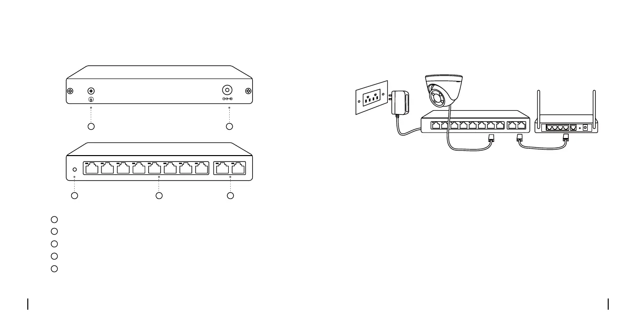
Product Introduction Connection Diagram
DC IN
UPLINKPoEPoE Switch
POWER
DC IN
UPLINKPoEPoE Switch
POWER
3 54
1 2
Grounding Screw
Gigabit Ethernet Uplink Ports
Power LED
DC Port
10/100Mbps Downlink PoE+ Ports (Max. 30W per port)
1
2
3
4
5
1. Power on the PoE switch with the provided power adapter.
2.ConnectoneendofanEthernetcabletotheuplinkportonthePoE
switch, and the other end to a router.
3. Connect your devices to the PoE+ ports on the switch via another
Ethernetcable.
 Loading...