The handlebar has been pre-assembled together with brake levers, shifter levers and
grips. Be sure that the longer cable is xed to the right lever (rear brake) and shorter
cable to the left (front brake). (NOTE: In some areas, such as the UK, the cables are
required to be arranged in the opposite way).
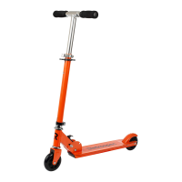
Your e-bike may be tted with an adjustable stem, a standard quill stem, or a
threadless stem (Refer to Fig. 12). Regardless of stem type, always check that all the
bolts are tight before riding. Respect the stem type and follow the instruction below:
1. For Quill Stem: Insert the handlebar stem into the fork steer tube to the minimum
height line that is marked on the side of the handlebar stem. It may be necessary to
loosen the stem Expander Bolt so that the stem can slide into the fork tube, until you
get your desired height of the handlebar stem.
For Threadless Stem: Slide the stem over the fork steer tube.
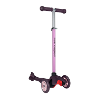
2. Align the handlebar stem with the front wheel (See Fig. 13). Securely tighten the stem
bolt(s). Note: Some models require a 6mm hex key. (Tightening torque: 18N.m or 14foot
lbs.torque).
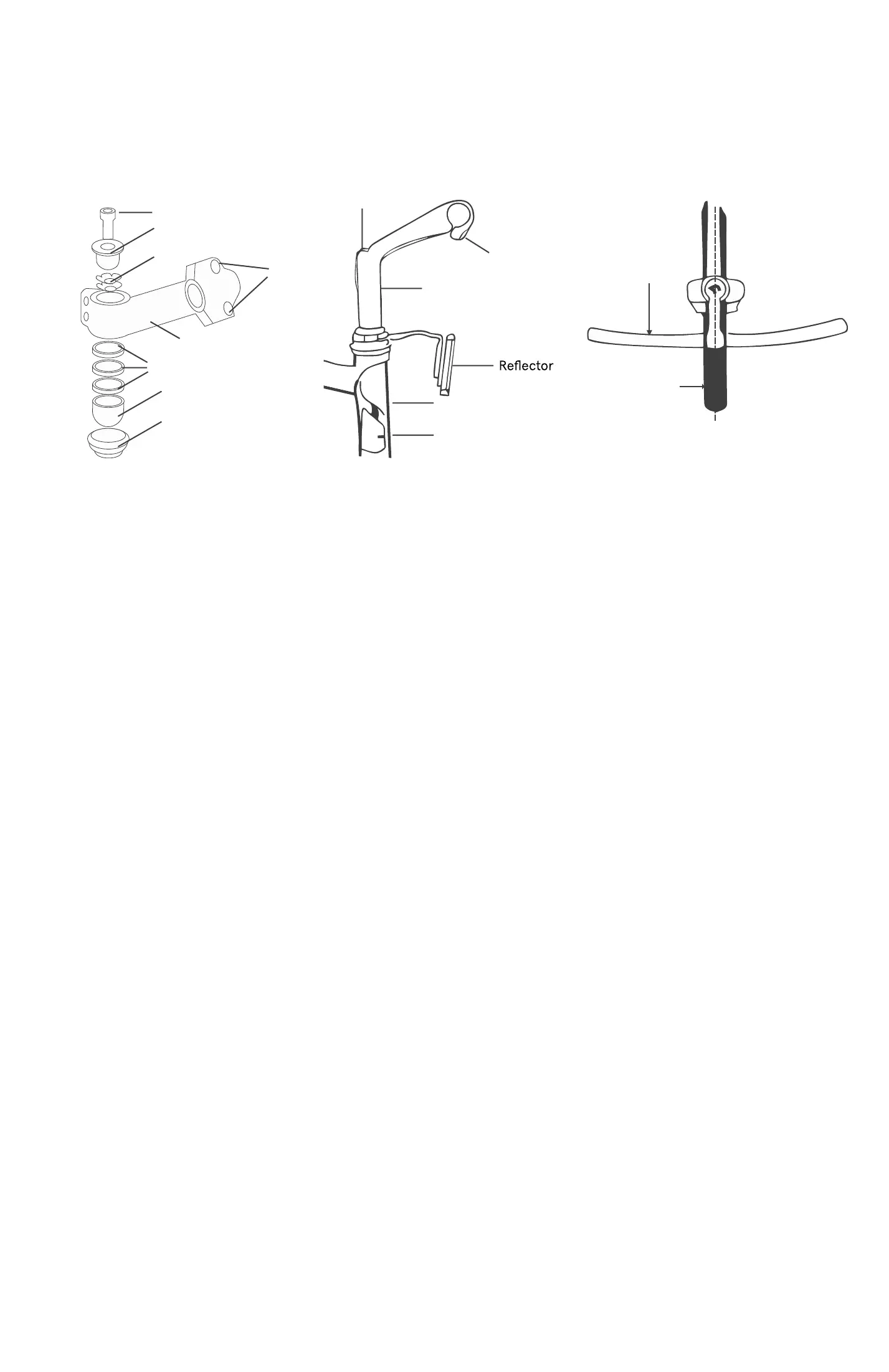
3. Positioning the Handlebar:
• Loosen the stem handlebar clamp bolt (Quill) or hex bolts (Threadless).
• Position the handlebar at the desired angle. Make sure the handlebar is in the
center of the stem handlebar clamp.
• Tighten the handlebar clamp bolt (tightening torque: 18N.m or 14footlbs.lbs).
4. Be sure that your handlebar and stem assembly is properly tightened before riding.
The handlebar and stem should not rotate in the stem up or down or in the fork from
left or right. (Fig. 13)
Step 5: Installing Pedals (Refer to Fig. 14)
The pedals are marked with either a “R”(Right) or “L” (Left) on the threaded end of the
pedal axle.
Screw the pedal marked by” R” into the right side of the crank assembly (chain side of
bicycle). Turn the pedal (by hand) in the clockwise direction. Tighten securely with a
15mm open-end, 15mm pedal specic wrench, or adjustable wrench (tighten to torque:
34N.m or 26 lbs).
Screw the pedal marked by “L” into the left side of the crank assembly. Turn the left
pedal (by hand) in the counterclockwise direction. Tighten securely with a 15mm open-
end, 15mm pedal specic wrench, or adjustable wrench (tighten to torque: 34N.m or 26
lbs).
9 10
Compression Bolt
Compression Cap
5 Star Washer
Stem
Bolts
Extension
Fork Tube
Expander Wedge
Expander Bolt
Spacers
Bearing Seat
Top Cups with
Bearings Inside
Fig. 9
Handlebar Stem
Handlebar
Clamp Bolt
Handlebar
Front Wheel
Center Line
Fig 10. Handlebar and Handlebar Stem Assembly
Fig. 11 Attaching Pedals
Step 4: Handlebar & Handlebar Stem Assembly (Refer to Figs. 12 & 13)
Fig. 12
Threadless: Quill:
Fig. 14
Fig. 13
 Loading...