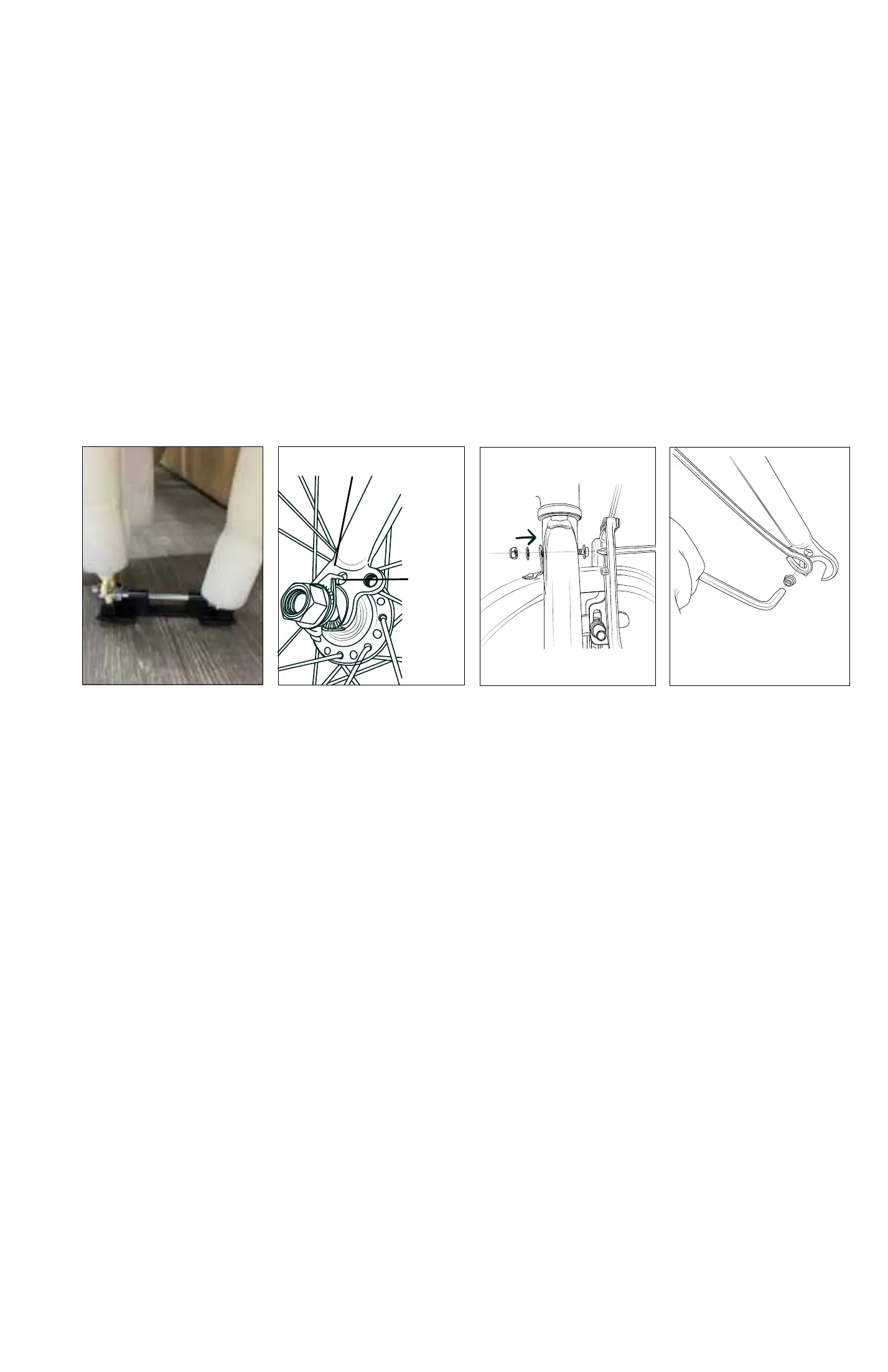
Adjustment
Nut
Closed
Open
Fig. 8 Opening and Adjusting a Quick Release
Step 2: Front Wheel & Front Fender Installation
2.1 Installing the Front Wheel
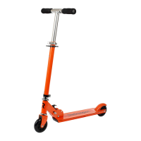
1. Remove the plastic dropout protector from the metal shipping axle. (Fig. 6)
2. Unscrew and remove the metal shipping axle from the fork dropouts. use photo
attached. You can discard or save this device in case you ship or transport your bike
with the front wheel removed. Suggest you inate the tire to make centering the wheel
in the fork easier (point 4 below).
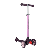
3. Loosen the axle nuts on the front wheel. Lift the front of the bike and insert the front
wheel into the fork dropouts (a helper can make this easier). Insert the tab of the safety
washers into the small holes on the outside of the fork dropouts. (Fig. 7)
4. Inspect the wheel to make sure it is centered in the fork. Tighten each axle nut a
little at a time (15mm or adjustable wrench), alternating between sides, until each axle
nut is properly tightened.
2.2 Installing the Front Fender
1. Locate the long bolt, washer, and nut which will either be in the parts bag/box or
inserted in the top of the fork.
2. Slide the fender in place from the back of the fork. Insert the long bolt through the
top/center fork hole from the front of the bike. At the rear of the fork hole, place the
bolt through the fender mounting tab with the washer and nut. While pushing the
fender tab up as far as it will go, tighten the bolt and nut to secure the fender to the
top of the fork (Fig. 8)
3. Position the fender braces to the mounting holes on the fork dropouts. It’s okay to
squeeze inward as these braces are designed to be pliable. Partially thread the screw
through the fender brace end hole and into the dropout - repeat for the other side.
When both braces are partially attached, tighten the brace screws to complete the
install (Fig. 9)
4. If the fender is not straight, or rubbing the tire, that’s okay! As mentioned above, the
fender braces can be bent to center the fender. Gently adjust the fender by hand until
it’s straight.
NOTE: Rear Fender Adjustment: The rear fender is installed at the factory and should
be good-to-go. However, it may require some small adjustment due to shipping. Follow
2.2 step 4 to straighten as necessary or a combination of loosening the brace end
bolts, retightening, and centering.
Fig. 6
Fig. 7
Fig. 9
Fig. 8
Tip of Seat
Seat Clamp
Seat Post
Seat Tube
Seat Clamp Nut
Minimum
Insertion Line
Top Tube
Seat Post Binder
Bolt and Nut
Fig. 7 Seat Assembly
Fig. 10
WARNING! The seat post must be inserted into the seat tube at a depth where the
release lever. The tightness of the
lever is adjusted by rotating the
adjustment nut opposite the quick
release lever. Turn the nut by hand to
adjust the tension while holding the
lever stable.
Fig. 11
Safety Washer
Fork
Dropout
Small Hole
7 8
minimum insertion line is not visible!
3.2 Inserting the Seat/Seatpost Assembly Into the Frame Seat Tube, Quick-Release
Seatpost Clamp:
1. Open the seat post quick release lever (Fig.11). Insert the seat post into the seat tube
to sucient depth so that the minimum insertion line is no longer showing.
NOTE: The lever should require some force to close. If it closes too easily and does not
hold the seat post in place, or if the eort to close the clamp is too great, adjust the
clamping force by loosening or tightening the adjusting nut on the side opposite the
lever.
2. When you are satised with the height of the seat post, close the seat post quick
Step 3: Seat Assembly (Refer to Fig. 10)
3.1 - Assembling the Saddle onto the Seatpost:
1. Loosen the seat clamp nuts - both sides equally.
2. Insert the seat post into the seat clamp. Make sure the seat post is rm against the
seat clamp limit.
3. Re-tighten the seat clamp nuts equally on both sides (hand tight).
4. Insert the seat post into the frame seat tube and rotate the seat until the tip of
the seat is directly above and in-line with the top tube of the frame. You can nish
tightening the seat now or after Step 3.2. Do not sit, or test saddle until completing
Step 3.2!
 Loading...