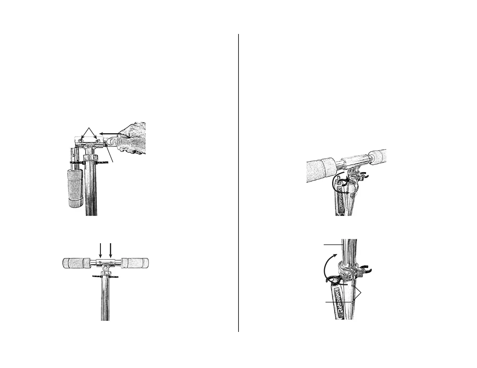
Fig. 6
1. Insert the two Handgrips by pressing the spring-loaded Lock Buttons and
inserting into the T-Bar (Fig. 5).
2. Make certain BOTH Handgrips are securely locked into the T-Bar (Fig. 6).
When correctly engaged the Hand Grips will not rotate or move sideways.
When correctly engaged the spring-loaded Lock Buttons are clearly visible
in the Lock Holes on the T-Bar.
STEP 2: UNFOLDING HAND GRIPS
Fig. 7
Fig. 8
1. Open handlebar Quick Release Lever by pulling it away from the handlebar
assembly (Fig. 7).
2. Slide T-Bar upwards to one of the two lock button hole positions – be sure the
Lock-Button fully engages into the desired Lock-Hole (Fig. 8).
3. Lock close the Quick Release Lever tightly against the handlebar assembly (Fig. 8).
The lever should begin to oer resistance at about the half way point in its travel. The
lever should require some force to close. If it closes too easily, or if the eort to close
the clamp is too great, adjust the clamping force by loosening or tightening the
adjusting nut on the side opposite the lever.
STEP 3: ADJUSTING HANDLEBAR HEIGHT
LOCK HOLES
LOCK
BUTTON
OPEN
Fig. 5
T-BAR
CLOSE/LOCK
LOCK
BUTTON
LOCK BUTTON
HOLES (2)