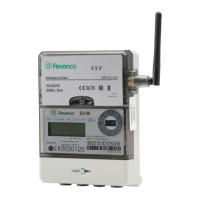
The Orsis S2-M is a single-phase energy meter with an integrated communication module, designed for remote monitoring of electricity consumption and generation. This device is suitable for both residential and commercial applications, particularly in scenarios involving solar panel installations where both imported and exported energy need to be tracked.
Function Description:
The primary function of the Orsis S2-M meter is to accurately measure and record electrical energy. It can track both cumulative import (energy consumed from the grid) and cumulative export (energy generated and sent back to the grid). The integrated WAN module enables wireless communication, allowing for remote data collection and monitoring. This is particularly useful for billing, energy management, and verifying the performance of generation systems like solar panels. The meter also includes a reverse run counter, which tracks instances where current flows backward through the meter, indicating either an incorrect wiring setup or, in the case of an export meter, energy being sent back to the grid.
Important Technical Specifications:
- Voltage: 165-240VAC (for the WAN module), 230V (for the meter)
- Current: 0.5-10 (100)A
- Frequency: 50/60Hz (for the WAN module), 50Hz (for the meter)
- Operating Temperature: -25°C to 55°C
- Accuracy Class: kWh Cl.B EN50470, kWh Cl.1 IEC 62053-21
- Impulse Rate: 1000 imp/kWh
- Communication: Wireless (WAN module), Optical communications (indicated by display icon)
- Certifications: CE0678, CEM15 0120
Usage Features:
The Orsis S2-M meter features a clear LCD display with various indicators to provide real-time information about its operation and the energy flow.
-
Display Indicators:
- Number display: Shows numerical values for readings.
- Display page: Indicates the current screen being viewed.
- Reverse Run Indicator: Alerts to reverse current flow.
- Error/Alarm: Signals system errors or alarms.
- Wireless Communications available: Confirms the presence of a wireless network.
- On optical communications: Indicates active optical communication.
- Energy flow – Import: An arrow pointing right signifies energy being imported from the grid.
- Energy flow – Export: An arrow pointing left signifies energy being exported to the grid.
- Counter: Indicates a counting function.
- On wireless communications: Confirms active wireless communication.
-
Display Index Screens: The meter automatically scrolls through four main display screens:
- Segment Test Display: Ensures all LCD segments are functioning correctly.
- Cumulative Import (kWh): Shows the total energy consumed from the grid, indicated by an arrow pointing to "Import."
- Cumulative Export (kWh): Shows the total energy generated and sent back to the grid, indicated by an arrow pointing to "Export."
- Reverse Run Count: Tracks the number of times current has flowed backward through the meter. This is crucial for generation meters to detect incorrect wiring or for export meters to confirm energy export.
-
LED Description (on the communication module): The communication module has three LEDs:
- PWR (Power): Always On when the system has normal power supply.
- REG (Registration Status): Always On when registered, Always Off when not registered.
- ERR (Error Indication): Flashes to indicate specific errors. The number of flashes corresponds to a defined error list.
-
LED Error Definition List (for ERR LED):
- Always Off: Registered.
- 1 Flash: SIM card requires changing.
- 2 Flashes: Meter not connected to module.
- 4 Flashes: External Flash Read-Write Error.
- 5 Flashes: GSM Module not started.
- 6 Flashes: GSM Module serial communication error.
- 7 Flashes: External EEPROM Read-Write error.
- 8 Flashes: Meter Connection Error (Failure to get correct data).
- 9 Flashes: GSM Module Initialisation Failure.
- 10 Flashes: Dialling Failure.
- 11 Flashes: Exceptional Socket Interruption.
- 12 Flashes: Load balance log in error.
- 13 Flashes: Communication server log in failure.
- 14 Flashes: Registration Failure.
Maintenance Features:
- Meter Commissioning Phase: Before leaving the site, the commissioning engineer must contact Orsis support to confirm that communication paths between the meter and module via GPRS are operational. The metering system is not considered operational until Orsis support confirms all communications are connected.
- SIM Card Replacement: The device allows for SIM card replacement, which is a key maintenance feature for ensuring continuous communication.
- Isolate Power: Ensure power to the meter is switched OFF.
- Access SIM Card Cover: Locate the barcode sticker on the top edge of the module, which contains the SIM card number. Peel back this sticker to reveal a small screw.
- Remove Screw: Remove the small screw underneath the sticker.
- Slide Cover: Slide the grey plastic cover upwards to expose the SIM card slot.
- Remove Old SIM: Press the existing SIM card inwards; it will spring out of its cradle for removal.
- Insert New SIM: Insert the new SIM card into the slot and press it inwards until it clicks and locks into place.
- Close Cover: Slide the grey plastic cover back down.
- Refit Screw: Refit the small screw, tightening it to secure the cover (do not overtighten).
- Replace Sticker: Stick the barcode sticker back down over the screw.
- Power Up: Power up the meter. The successful connection is indicated by two green LEDs (PWR and REG) lighting up on the module.
- Confirm Connection: Contact Orsis support to verify the connection after SIM card replacement.
Important Warning: Do not remove the communication module from the meter, as this will void the warranty and may damage the module.