EasyManua.ls Logo

Revolution PICAXE-08 - User Manual

Revolution PICAXE-08
38 pages
Print Icon
To Next Page IconTo Next Page
Loading...
1
PICAXE-08 ALARM PROJECT
revolution
© copyright 2002 - AXE102 Alarm Student Project Notes Version 1.1
Revolution Education Ltd. Email: info@rev-ed.co.uk Web: www.rev-ed.co.uk
1
Supported by:
ALARM SYSTEMS
What is a microcontroller?
A microcontroller is often described as
a 'computer-on-a-chip'. It can be used
as an ‘electronic brain’ to control a
product, toy or machine.
The microcontroller is an integrated circuit
("chip") that contains memory (to store the program), a
processor (to process and carry out the program) and input/
output pins (to connect switches, sensors and output devices like motors).
Microcontrollers are purchased 'blank' and then programmed with a specific control
program. This program is written on a computer and then 'downloaded' into the
microcontroller chip. Once programmed the microcontroller is built into a product to
make the product more intelligent and easier to use.
Example use of a microcontroller.
Almost all modern buildings are fitted with some type of alarm. For
instance a fire detection system may have a number of smoke sensors
to detect the smoke from a fire.
However many alarm systems are also safety systems - for instance an
alarm system on an oil rig may monitor the temperature and pressure
of the crude oil as it is being extracted and automatically shut
the system down if a fault is detected. This ensures the safety of
both the workers and the environment around the oil rig.
All systems are made up of input and output devices. Often
these devices are connected to a microcontroller that interprets
the information from the sensors and switches the outputs on
and off at the correct time.
In the case of a fire alarm system the inputs may be smoke
sensors and the keypad on the front of the control panel. The
output devices are the display on the control panel as well as
the external siren and strobe light. The microcontroller is the
'brain' of the system.
Microcontrollers are powerful electronic components that have a
memory and can be programmed to switch things on and off in a
special sequence. The microcontroller in the fire alarm, for
instance, has been programmed to switcyh the siren on and off
when the smoke sensor has detected fire.
1
23
4
56
7
89
*
0#
A
PICAXE
ALARM
B
C
D
Question and Answer IconNeed help?

Do you have a question about the Revolution PICAXE-08 and is the answer not in the manual?

Summary

Alarm Systems Overview

Understanding Microcontrollers

Defines microcontrollers and their use in alarm systems, including their function as an 'electronic brain'.

System Block Diagrams

Introduction to PICAXE System

Explains the PICAXE system for simplifying microcontroller programming through BASIC or flowcharts.

Designing Your Own Alarm

Project Design Brief and Specifications

Outlines the project goals, design requirements, and specific features for the alarm system.

Alarm Application Examples

Illustrates various potential use cases for alarm systems, such as fire or burglar alarms.

Microcontroller Functionality

Microcontrollers in Electronics

Details microcontroller definition, applications, and their role as the 'brain' in electronic circuits.

Programming Microcontrollers

Program Writing and Transfer Methods

Covers methods for writing programs (flowcharts/BASIC) and transferring them to the microcontroller.

Powering the Circuit

Battery Selection and Handling

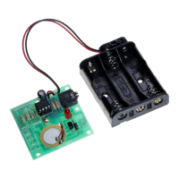
Guides on battery types, sizes, and safe handling practices for the project.

Safety and Handling Precautions

Electrical Safety and Battery Use

Covers general safety, short-circuiting risks, and proper use of battery snaps and boxes.

Light Emitting Diode (LED)

LED Basics, Applications, and Connection

Defines LEDs, their uses as indicators, and how to connect them with a protective resistor.

Testing LED Connection

LED Connection Verification

Provides a program and checklist to test the LED connection and functionality.

Sound Output Components

Piezo Transducers and Buzzers

Defines piezo transducers, buzzers, their differences, and connection methods.

Testing Piezo Connection

Piezo Connection Verification

Provides a program to test the piezo sounder and troubleshoot issues.

Transistors

Transistor Function and Application

Explains transistors as electronic switches, their uses, and interaction with motors and noise.

Testing Transistor Circuits

Transistor Testing and Output Devices

Details testing transistor circuits with a buzzer and lists common output devices.

Digital Sensors: Switches

Switch Types, Uses, and Symbols

Defines digital sensors (switches), their types, applications, and graphical symbols.

Switch Integration and Testing

Using and Testing Switches

Guides on wiring switches into circuits and testing their functionality.

Light Dependent Resistor (LDR)

LDR Definition, Applications, and Use

Explains LDRs, their resistance change with light, applications, and measurement modes.

Using LDRs as Sensors

LDR as Digital or Analogue Input

Details using LDRs as simple on/off switches or as analogue sensors for light levels.

Testing LDR Inputs

Digital and Analogue LDR Test Procedures

Provides programs to test the LDR's digital and analogue input capabilities.

Section 3: Programming Flowcharts

Flowchart Editor and Download Guide

Instructions for using the flowchart editor to draw and download programs.

Flowchart Editor Tools

Using Flowchart Editor Tools

Explains the functionality of tools like Select, Zoom, and Pan within the editor.

Flowchart Drawing Techniques

Line, Label, and Shape Connection

Details techniques for drawing lines, adding labels, and connecting flowchart shapes.

On-Screen Flowchart Simulation

Simulating Flowcharts in Editor

Describes how to simulate flowcharts on-screen to test logic and inputs.

Flowchart Management and Download

Saving, Printing, and Converting Flowcharts

Procedures for managing flowchart files, including saving, printing, and conversion.

Section 4: Programming in BASIC

Introduction to BASIC Programming

Highlights the advantages of BASIC over flowcharts and basic syntax elements.

Downloading a BASIC Program

Detailed BASIC Program Download Steps

Step-by-step instructions for connecting and downloading a BASIC program to the PICAXE.

Programming Editor Quick Reference

Editor Functions and Shortcuts

Summarizes common editor functions, toolbar shortcuts, and file operations.

The Alarm PCB

PCB Overview and Circuit Diagram

Explains the PCB layout, block diagram, and the overall circuit diagram.

PCB Pin Numbering Clarification

Clarifies the difference between microcontroller chip legs and input/output pin numbers.

Building the Alarm PCB

Components, Tools, and Resistor Codes

Lists necessary electronic components, tools, and the resistor colour code chart.

Soldering the PCB

Soldering Steps and Best Practices

Provides detailed steps and tips for successfully soldering components onto the PCB.

PCB Assembly Steps

Component Placement and Soldering Order

Specific instructions for placing and soldering various components onto the PCB.

Testing the Assembled Circuit

Pre-Power Checks and Connections

Verifying solder joints, component placement, and battery connection before powering up.

Program Download and Output Testing

Testing LED and Output Devices

Procedures for downloading programs to test the LED and output devices like buzzers.

Input Device Testing

Testing Piezo and Switch Inputs

Procedures for testing the piezo sounder and digital input switch functionality.

Testing the LDR Input

LDR Test Procedures

Provides programs to test the Light Dependent Resistor as both digital and analogue inputs.

Section 6: Program Ideas

Example Alarm Program Explanations

Overviews of two example programs for developing custom alarm functionality.

Revolution PICAXE-08 Specifications

General IconGeneral
Program Memory256 bytes
RAM14 bytes
I/O Pins5
Max Clock Speed8 MHz
Programming InterfaceSerial