The REVOV R200 battery is designed for parallel operation only -do not arrange in series for increased
voltage. Series arrangement can result in damage to the Batteries and will void warranty!
Do not discharge battery below Low Voltage Disconnect voltage. Do not discharge battery at rates greater
thanmaximumcontinuouscurrent.
• Settings are only a guide as to what must be on the Battery/BMS. Please ensure that the DC circuit loses
are considered during Inverter setup. Inverters are also not calibrated instruments.
• The REVOV R200 system has a self-managing Battery Management System. The system still requires the
user to input settings onto the inverter unless Can communication is supported.
• Eachbatterybankistobefusedonbothpositiveandnegativewith125A(MaxratedDC)fuse.
Preferably trip-breaker or in-line fuses.
• Donotcrossthepositiveandnegativeterminals.Installthepositivecablefirst.Pleasemakesurethe
terminalsarenotconnectedtoanymetalmounting,fixture,orbodyparts.
• Each battery is to be coupled to a common DC copper busbar if using more than 1 battery. Care must
be taken with Parallel batteries with different open voltage as this may cause reverse currents, which
coulddamagethebatteries(donebyqualifiedinstallersonly).
• The R200 battery is designed to sit in a cabinet, or mount on the wall. It is recommended to put the
batteriesona location higher than the groundtoavoidwaterdamageorfloods.
• Safeandreliableinstallationrequirestrainedandcertifiedtechnicians/installerstodesignandinstall
systems.
* Battery will auto-start. Green LEDs of the system should run, if not, press circular ON/OFF button softly into the
ON position (depressed). If red light engages on start-up, contact REVOV for assistance.
The Battery BMS provides multiple level protection function:
• Over Charge Voltage Protection
• Over Discharge Protection
• Over Current Protection for Discharge Via Thermal Control
• Short Circuit Protection
• ON/OFF Switch
If batteries enter a self-protective mode, negligible voltage readings will be present on the LCD until the
unit resets. In some instances, after a prolonged shut down, or a draw to a low voltage, a charge might
need to be manually applied to the energy storage bank. Should this occur, please contact REVOV
for technical support. REVOV Lithium Batteries are designed to remain robust and safe under most
circumstances.
Precautions
Warranty is void if any of these are not adhered to.
1. Do not immerse the battery in water.
2. Donotuseorstorethebatterynearsourcesofreorheater.
3. Do not reverse the positive (+) or negative (-) terminals.
4. Do not connect the battery directly to wall outlets.
5. Donotputthebatteryintoareorapplydirectheattoit.
6. Do not short-circuit the battery by connecting wires or other metal objects to the positive (+) and
negative (-) terminals.
7. Do not pierce the battery casing with a nail or other sharp objects, break it open with a hammer,
or step on it.
Parameter set up guide in Charger/Inverter Before commissioning the energy storage system,
the appropriate controller and inverter settings must be programmed as per the manufacturer’s
recommendations.
Consult the Inverter manufacturer’s manuals and/or access REVOV technical support. Although REVOV
Lithium batteries can perform at high rates and depths of discharge within a very wide temperature
range,inordertoachieveextendedlifecyclesandtocomplywiththeWarranty,thisguidelinedocument
must be followed.
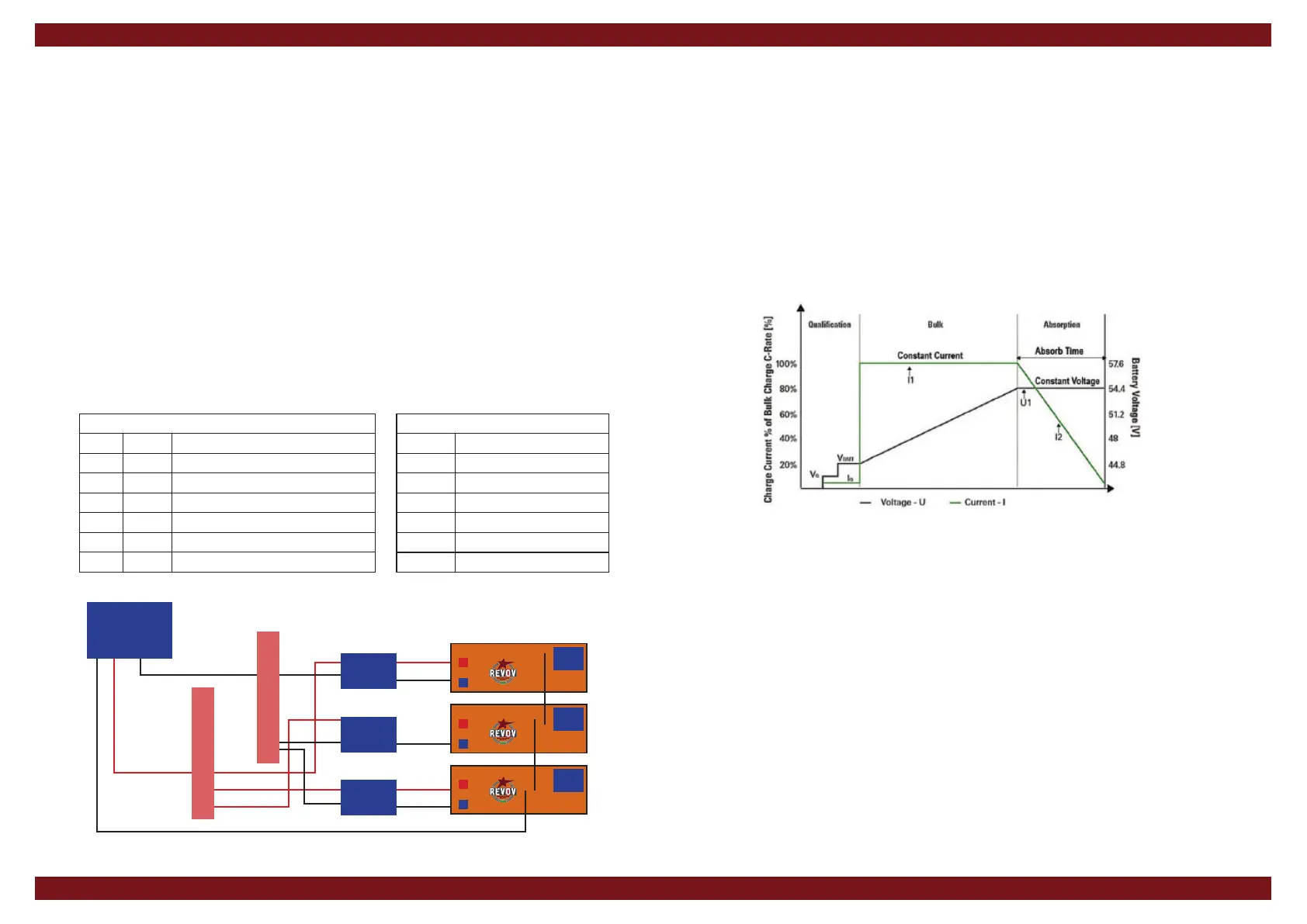
Understand Charge Stage
1. Bulk Charge: Charge at Constant Current (CC) to Bulk/Absorb Voltage.
2. Absorption Charge: Maintain Constant Bulk/Absorb Voltage (CV).
3. Terminate when charge current drops below 0.05C or 46.5V.
4. Unlike Lead Acid batteries, Lithium Ferro
Phosphate batteries do not require Float Charge.
5. Do not enable Equalisation function in the inverter;but do set up the Equalisation parameters to
Bulk values.
Dip Switch Guide (Master and slaves)
System Address Example
1
1000
First jumper up, rest down
2
0100
Second jumper up, rest down
3
1100
First two jumpers up, rest down
4
0010
Third jumper up, rest down
5
1010
First and Third jumper up, rest down
6
0110
Second and Third jumper up, rest down
BMV Settings
Number Setting
1 Ah of total batteries installed
2 0.3V lower that absorption
3 4%
4 4 min
5 1.05
6 0.9
Always install fuse protections
DC cables equal length
R200 Battery units 1 to 3...CAN communication cable
+ ve Copper BUSBAR
Fuse/
Breaker
Fuse/
Breaker
Fuse/
Breaker
- ve Copper BUSBAR
INVERTER
SYSTEM


 To Previous Page
 Loading...