Thomas
®
XTSR52 Installation and Maintenance
(Page 11 of 13) Sizes 494-5258
CP3-002
September 2017
Supersedes 09-2016
Rexnord
5555 S. Moorland Rd., New Berlin, WI 53151-7953
Phone: 262-796-4060 Fax: 262-796-4064 www.rexnord.com
8.13 Slightly tighten all locknuts using an alternating progressive pattern on each disc pack as shown in Figures 13 and 14 making sure the disc pack
is not distorted and all the bolts are fully seated. Tighten each locknut to the appropriate torque value shown in Table 6, using an incremental
torque in a progressive alternating pattern as shown in Figures 13 and 14.
As a guide, measure the distance between flanges known as dimension “N” shown in Figure 7 and given in Table 4.
PRECAUTION
Remove any dust deposits from the coupling components and the coupling elements in an appropriate way for explosive environments.
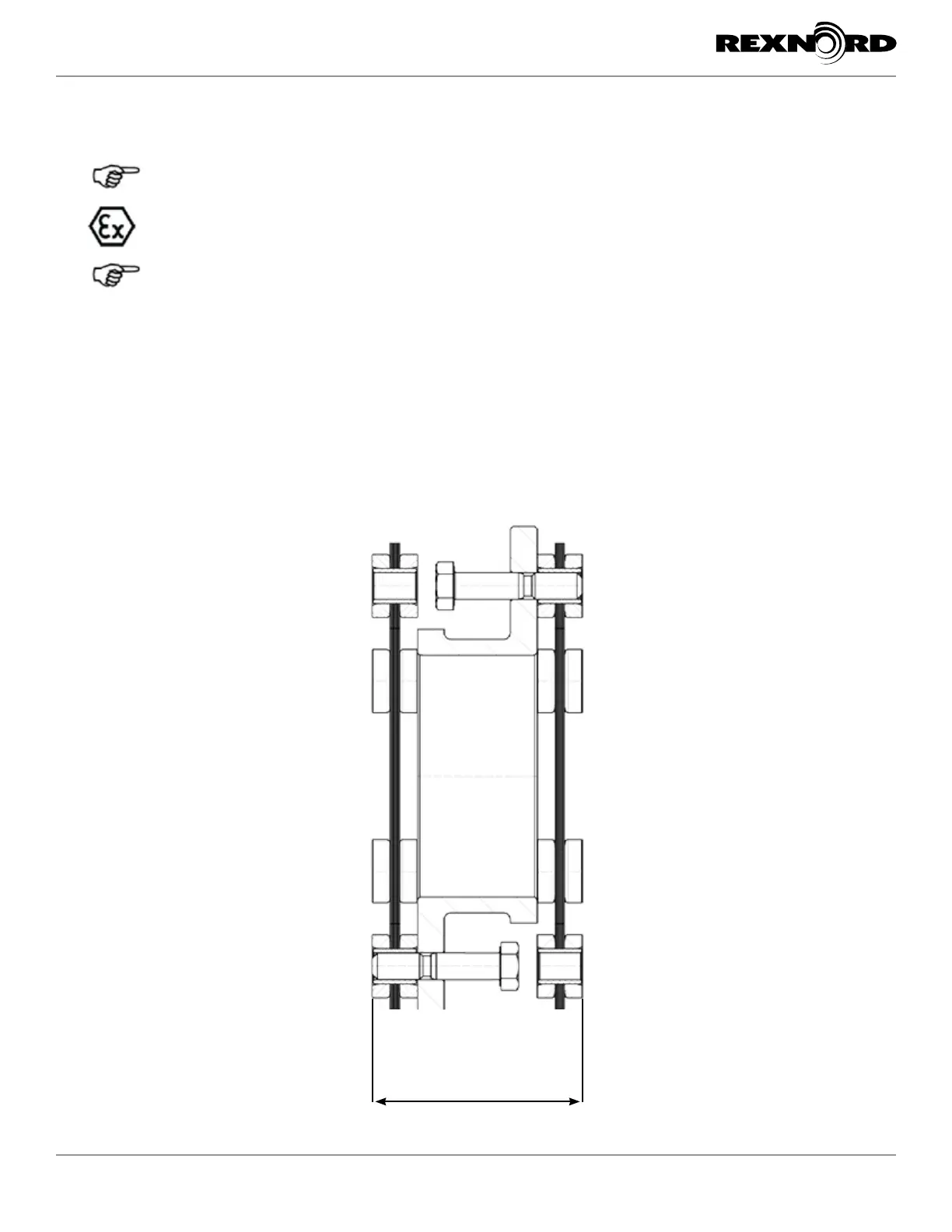
If your coupling utilizes a short center member with scalloped flanges (clearance hole area removed) follow these supplemental
instructions to aid in assembly.
8.14 In the event the coupling utilizes a scalloped version center member you will need to pre assemble the disc packs to the center member before
installing it between the mounted hubs as shown in Figure 12.
8.15 Place Disc against the scalloped flange of center member and align the bolt holes of the disc pack to the holes in the spacer flange as shown in
Figure 14.
8.16 Start bolt through bolt hole in spacer flange until body of bolt is in contact with disc pack washer. The threaded portion of the bolt is not exposed
on other end of disc pack.
8.17 Repeat on other side of spacer for remaining bolt holes.
8.18 Place center member between mount hubs and push pre-installed bolts through disc pack and into clearance holes of mounted hubs.
8.19 Continue spacer installation by following instructions 8.6 through 8.12.
Figure 12 - Short “C” Length Scalloped Center Member
“C” Length
 Loading...