Page 8
16
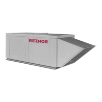
(406mm)
1-7/8(48mm)
4
(102mm)
2 x 6 Wood Nailer
1-1/2 x 3 lb
Fiberglass
Flashed by the
installer (flashing must
be under lip of curb)
Lag Screw
Cap
Screws
FIGURE 6 - Option CJ3
Roof Curb Cross Section
and Corner Detail
Corner
Detail
Curb
1. If installing an Option CJ3 curb, follow these instructions. If installing a
field-supplied curb, the curb must be level and must be sealed to the
system curb cap.
2. Position the roof curb end assemblies and side assemblies as shown in the
drawing in FIGURE 5, page 7. Fasten with bolts and lag screws as
illustrated in the corner detail (FIGURE 6).
8. Mounting
(cont'd)
3. If the system has a bottom discharge and/or a return air inlet, use the
sheetmetal screws to sub-assemble the dividers. Refer to the dimensions
in FIGURE 7 to appropriately position the roof curb dividers to create the
needed duct opening flanges. Attach the dividers to the roof curb with
sheetmetal screws. NOTE: If the system does not have a bottom discharge
and/or a return air opening, the dividers for an opening that is not going
to be used may be installed but are not required.
4. Check the assembly for squareness. The curb must be adjusted so that the
diagonal measurements are equal within a tolerance of ± 1/8".
5. Level the roof curb. To ensure a good weatherproof seal between the unit
curb cap and the roof curb, the roof curb must be leveled in both direc-
tions with no twist end to end. Shim as required and secure curb to the roof
deck before installing flashing.
6. Install field-supplied flashing.
7. Before placing the RDF unit on the curb, apply furnished 1/4" x 1-1/4"
foam sealant tape to the top perimeter surface of the curb, making good
butt joints at corners. The sealant tape must be applied to the curb rails to
Mounting on a Roof
Curb (cont'd)
Components in Option CJ3
Roof Curb (Refer to
FIGURE 5 to identify the
Item)
Roof Curb
Installation
Instructions
Com
onents in Roof Curb O
tion CJ3
Roof Curb Frame and Internal Ductwork Dividers (See FIGURE 5)
Item Qty
Description
1 2 Curb Front and Back Assemblies
2 2 Curb Side Assemblies
3 4 Full Width Curb Dividers -- two (2) for bottom discharge supply
air duct o
enin
and two
2
for o
tional return air duct o
enin
4 2 Cross Dividers for Bottom Discharge Supply Air Opening
5 2 Cross Dividers for Optional Return Air Opening
Roof Curb Corner Hardware
8 5/16" x 1" Lag Screws, P/N 16243
8 5/16" Lockwasher, P/N 1333
8 5/16" x 3/4" Hex Head Cap Screw, P/N 16247
8 5/16" Lockwasher, P/N 1333
8 5/16-18 Hex Nut, P/N 1035
Hardware to Assemble and Attach Dividers to make Ductwork Openings
64
For
Top
Two "Holes"
For
Bottom
Two "Holes"
#10 Sheetmetal Screws, P/N 11813
 Loading...