Form I-RDF, P/N 148384 (Rev 1), Page 9
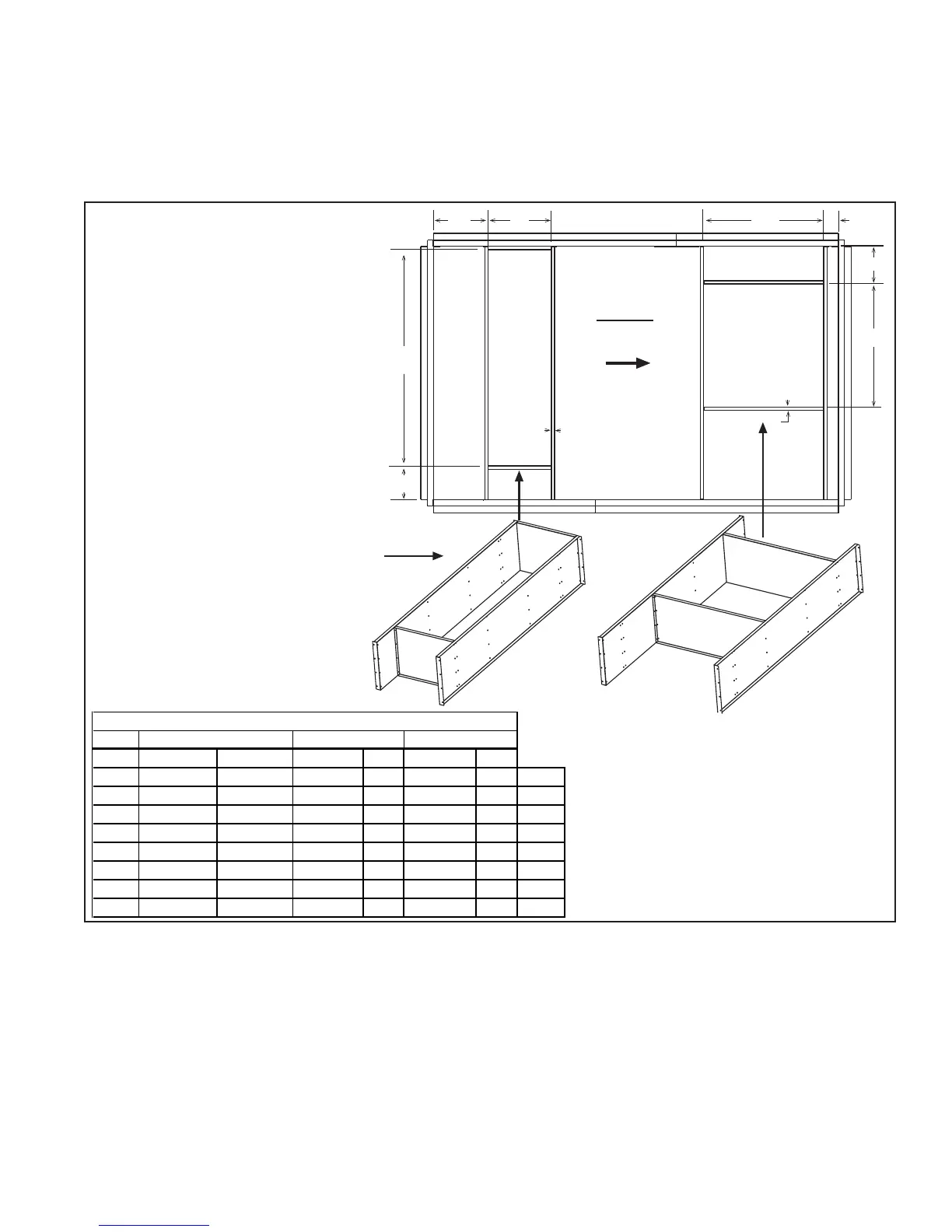
Airflow
Assembled Dividers for Optional
Return Air Ductwork in the Roof Curb
Field-supplied ductwork may be either
dropped in from the top resting on
the top flange or be attached to the bottom
flange, using the dividers as ductwork.
Bottom
Discharge
Supply Air
Opening
(A x B)
Return
Air
Opening
(E x F)
A
C
B
D
E
F
G
H
3/4 (19)
3/4 (19)
Top View
FIGURE 7 - Divider Locations for
Bottom Ductwork Openings
NOTES:
Drawing is not proportional for all
sizes.
3/4" (19mm) measurement is the
width of the flanges where the roof
curb mates with the heater. Flange
surface must be sealed.
When cutting duct openings in the
roof, cut opening(s) 1” (25mm)
larger than duct size opening for
installation clearance.
9. Distribution of
Makeup Air
Makeup air can be introduced to the building either through distribution ducts
or through controlled pressurization with little or no ductwork. Makeup air
should be introduced and maintained using the lowest possible air velocity.
With ductwork distribution, this is accomplished using a multiplicity of dis-
charge openings over the greatest centerline distance. When a makeup air
system is automatically controlled to maintain a set building pressure, the en-
tering air will travel naturally toward the relief areas at the perimeter walls
using the building structure as the distribution ductwork.
Makeup air should enter at the highest point practical. By doing this, the fresh
air will entrain dust laden air at the ceiling and move it toward the point of
exhaust. Also, fresh air directed downward from the roof or ceiling will mix
with hot ceiling air resulting in improved distribution of heat in the building.
Sizes
inches mm inches mm inches mm
A
23-11/32 593 28-13/32 722 38 965
A
B
20-1/8 511 28-11/32 720 38 965
B
C
5 127 13-15/32 342 11-19/32 294
C
D
10-1/4 260 7 178 4-5/8 17
D
E
25-1/2 648 54-11/16 1389 66-3/4 1695
E
F
11-1/2 292 17-23/32 432 20-1/16 510
F
G
11-15/32 291 8 203 10-15/32 266
G
H
11-1/32 280 11-3/32 282 17-1/4 438
H
Roof Curb Duct O
enin
Dimensions (± 1/8" or 3mm)
1-20, 1-40, 1-50, 1-65 2-80, 2-120 3-180, 3-260
prevent water leakage into the curb area due to blown rain and capillary
action.
Also place the foam sealant tape on the perimeter of the top surface of the
duct opening(s), being sure to make good butt joints at corners. If install-
ing ductwork from the top, it is recommended that tape be put on again
after the ductwork is "dropped in", sealing below and above the duct
flanges.
 Loading...