Form I-RDF, P/N 148384 (Rev 1), Page 15
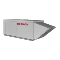
Increasing
Decreasing
Linkage to
Diaphragm
Low
Common
High
Span Adjustment
Span of
floating
contact
Switching action in the pressure null switch
Electric Box
Span
Adjust
Screw
Mounting Plate
Pressure Taps
Low
High
Pressure
Adjust
Screw
FIGURE 18 - Pressure Null
Switch included in Air
Control Options AR20 and
AR23
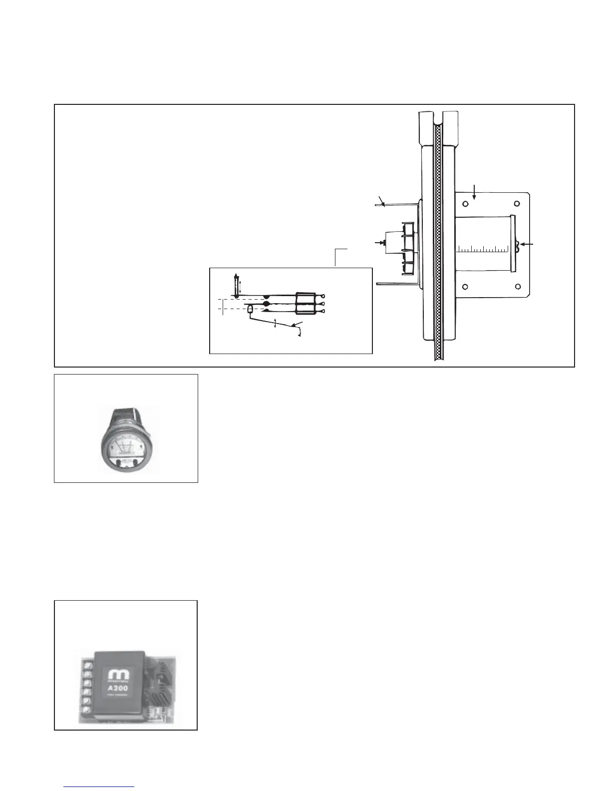
Optional Photohelic Pressure Switch (applies to
systems with Air Control Option AR36 for makeup
air only or AR37 for outside and recirculation air)
If the system includes Air Control Option AR36, the discharge damper is con-
trolled by a photohelic pressure switch. If the system includes Air Control
Option AR37, the photohelic pressure switch controls the return air damper.
The photohelic pressure switch is shipped separately.
The photohelic switch uses relays to control between high and low pressure
setpoints. When the pressure changes, reaching either setpoint, the beam from
an LED to the limiting phototransistor will be cut off by the helix-driven light
shield. The resulting signal change is electronically amplified to actuate its
DPDT slave relay and switching occurs. Pressure rating is 0" w.c. to .25" w.c.
Mount the switch with the scale vertical in a location where the ambient tem-
perature is between 20° and 120°F. Pneumatic pressure sensing lines may be
run any distance. Refer to the manufacturer's installation instructions and the
wiring diagram to install and connect this switch.
Optional Field-Provided Computer Control (applies
to systems with Air Control Option AR33 or AR34
and/or with Gas Control Option AG37 or AG51
If the system includes Air Control Option AR33, the discharge damper is con-
trolled by a field-supplied 0-10VDC or 4-20 milliamp signal. If the system
includes Air Control Option AR34, the computer controls the return air damper.
With AG37, the gas valve and burner modulation are controlled by the field-
supplied computer signal. With AG51, the gas valve and burner modulation
and outside air damper are controlled by the field-supplied computer signal.
Follow the signal conditioner manufacturer's instructions included with the
system for connecting to the field-provided control.
FIGURE 19 - Photohelic
Pressure Switch
IMPORTANT: To eliminate shipping damage to the
switch contacts, the manufacturer reduced the span
adjustment to zero before shipping. The span should be
adjusted prior to using the switch. (If the switch has been
installed, disconnect the vent tube so that the null switch
is in a neutral position.) Remove the switch electrical box
cover and while observing the contacts, turn the span
adjustment screw slowly in a clockwise direction. Con-
tinue turning the adjustment screw until you are able to
see gaps between the common and both the low and high
contacts. A minimum gap provides the greatest sensitiv-
ity. The wider the gap, the lower the sensitivity.
Adjustment of the Switch - The "high" actuation point of the null switch is
indicated on a calibrated scale secured to the transparent range screw enclo-
sure. Building pressure is set by turning the adjustment screw. The "low" ac-
tuation point is set by adjusting the span on the null by turning the span adjust-
ment screw. The span range is .01 to .03" w.c.
FIGURE 20 - Maxitrol
A200 Signal Conditioner,
P/N 134170
 Loading...