Page 16
Gas
Supply
Piping
Capacity of Piping
Cubic Feet per Hour based on 0.3" w.c. Pressure Drop
Specific Gravity for Natural Gas -- 0.6 (Natural Gas -- 1000 BTU/Cubic Ft)
Specific Gravity for Propane Gas -- 1.6 (Propane Gas -- 2550 BTU/Cubic Ft)
Length
Diameter of Pipe
of
1" 1-1/4" 1-1/2" 2" 2-1/2" 3" 4"
Pipe Natural Propane Natural Propane Natural Propane Natural Propane Natural Propane Natural Propane Natural Propane
20’ 350 214 730 445 1100 671 2100 1281 3300 2013 5900 3599 12000 7320
30’ 285 174 590 360 890 543 1650 1007 2700 1647 4700 2867 9700 5917
40’ 245 149 500 305 760 464 1450 885 2300 1403 4100 2501 8300 5063
50’ 215 131 440 268 670 409 1270 775 2000 1220 3600 2196 7400 4514
60’ 195 119 400 244 610 372 1105 674 1850 1129 3250 1983 6800 4148
70’ 180 110 370 226 560 342 1050 641 1700 1037 3000 1830 6200 3782
80’ 170 104 350 214 530 323 990 604 1600 976 2800 1708 5800 3538
90’ 160 98 320 195 490 299 930 567 1500 915 2600 1586 5400 3294
100’ 150 92 305 186 460 281 870 531 1400 854 2500 1525 5100 3111
125’ 130 79 275 168 410 250 780 476 1250 763 2200 1342 4500 2745
150’ 120 73 250 153 380 232 710 433 1130 689 2000 1220 4100 2501
175’ 110 67 225 137 350 214 650 397 1050 641 1850 1129 3800 2318
200’ 100 61 210 128 320 195 610 372 980 598 1700 1037 3500 2135
Note: When sizing supply lines, consider possibilities of future expansion and increased
requirements. Refer to National Fuel Gas Code for additional information on line sizing.
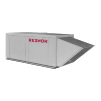
FIGURE 21 - Duct Smoke
Detector (cover removed)
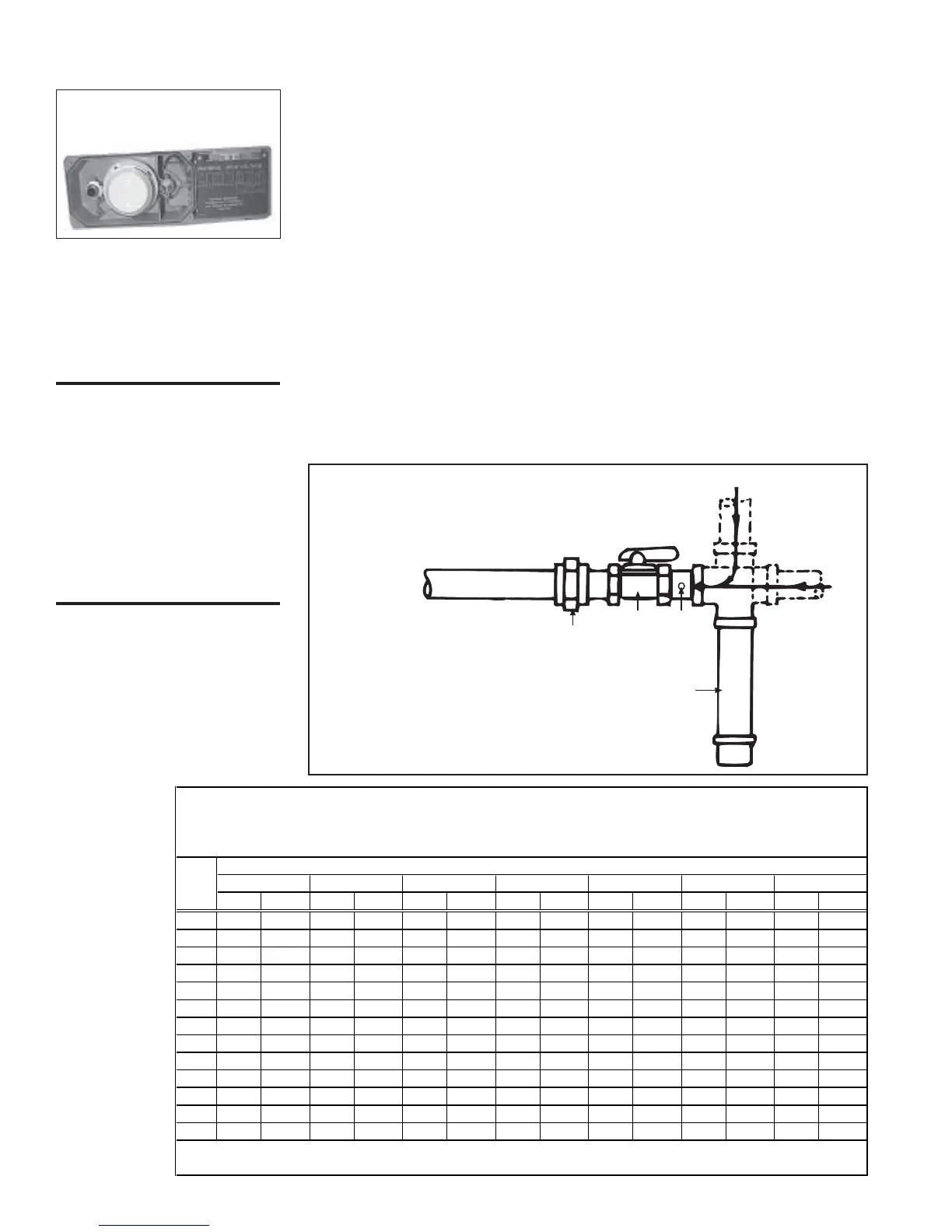
All piping must be in accordance with the requirements of the National Fuel
Gas Code ANSI/Z223.1 (latest edition) or CAN1 B149.1 and B149.2. Gas
supply piping installation must conform with good practice and with all local
codes. Read this section of the installation manual to determine the minimum
gas supply pressure required to provide a maximum gas capacity. Minimum
gas supply pressure is also stated on the heater rating plate. The heater mani-
fold terminates at the gas supply connection with a black iron pipe union. See
FIGURE 22. Local codes may require a 6" condensate trap. Gas connection is
either 1", 1-1/4", or 2" depending on the size of the system.
11. Gas Piping
and
Pressures
Optional Photoelectric Duct Smoke Detector
If the system has an optional photoelectric air duct smoke detector, the control
is shipped separately for field installation. The sensor must be field-mounted
in the discharge duct and electrically connected in the blower section electrical
box.
Follow the manufacturer's instructions and the wiring diagram for mounting
and connecting the control.
WARNING: High
pressure testing of
supply lines is
acceptable, provided the
supply line has been
disconnected from the
unit and the pipe end is
capped. See Hazard
Levels, page 2.
From Gas
Supply
From
Gas
Supply
6 Drip Leg
NOTE: Connections
shown are by the installer.
To Burner
and Controls
Manual
Gas Valve
A manual shutoff valve and an adapter with a 1/8"
NPT plugged hole for test gauge connection must
be installed immediately upstream of the gas
supply connection to the appliance.
Ground
Joint
Union
1/8
NPT
NOTE: To permit
burner removal this
nipple must extend
beyond the edge
of the heater.
FIGURE 22 - Gas Supply
Connection
10. Electrical Controls (cont'd)
 Loading...