HORNET
HORNETHORNET
HORNET-
--
-S1 / HORNET
S1 / HORNETS1 / HORNET
S1 / HORNET-
--
-S2 / HORNET
S2 / HORNETS2 / HORNET
S2 / HORNET-
--
-S3 (12
S3 (12S3 (12
S3 (12-
--
-32Vdc Receivers)
32Vdc Receivers)32Vdc Receivers)
32Vdc Receivers)
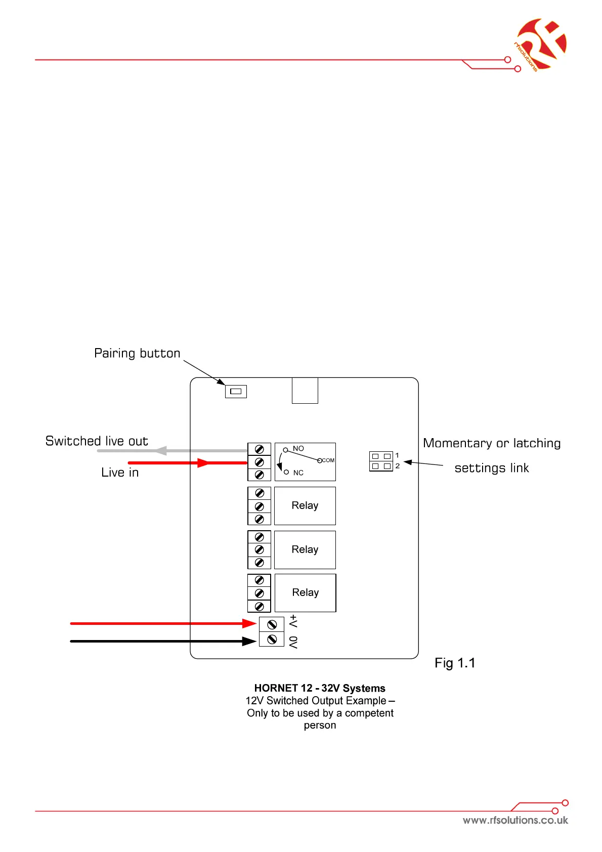
The HORNET system provides up to 4 isolated switches each capable of switching
up to 6A @230V
1. Open the enclosure by removing the two fixing screws from the base of the
enclosure and remove the antenna, the board should then slide out.
2. Wire the power as shown on Fig 1.1
3. Wire your chosen switch as required
4. Once the receiver is set-up; transmitter button 1 will switch relay 1 (button
two to relay two and so on). Each button press will change the state of the
relay (i.e. one press for on, one press for off).