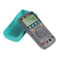
Measure Continuity
Measure Diode
Measure Resistance
1. Connect the black test lead to the COM Terminal and
connect the red test lead to the VHz Terminal;
2. Turn the rotary switch to the Resistance Mode, press
SELECT once to toggle to the Continuity Mode;
3. Touch the probes to the desired test points of the circuit;
4. The built-in beeper will beep when the resistance is lower
than 50Ω, which indicates a short circuit.
1. Connect the black test lead to the COM Terminal and
connect the red test lead to the VHz Terminal;
2. Turn the rotary switch to the Resistance Mode, press
SELECT twice to toggle to the Diode Mode;
3. Connect the red probe to the anode side and the black
probe to the cathode side of the diode being tested;
4. Read the forward bias voltage value on the display;
5. If the polarity of the test leads is reversed with diode
polarity or the diode is broken, the display reading shows
“OL”.
Caution:
a.Do not input voltage at the Continuity Mode.
1. Connect the black test lead to the COM Terminal and
connect the red test lead to the VHz Terminal;
2. Turn the rotary switch to the Resistance Mode, and the
display will show “OL”;
3. Touch the probes to the desired test points of the circuit
to measure the resistance;
4. Read the measured resistance on the display.
Caution:
a. Do not measure voltage that exceeds the MAX Value as indicated in the
Specifications;
b. Do not touch high voltage circuit during measurements.
 Loading...