READ THIS FIRST!
BEFORE INSTALLING THE SME240-1 2-20 CAREFULLY READ THE FOLLOWING
INSTRUCTIONS, ESPECIALLY THE SAFETY NOTES AND WARRANTY
CONDITIONS.
INTRODUCTION
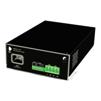
The RFI SME240-1 2-20 (battery charger/eliminator) provides a power output of 280 watt at
1 3.6 Volts. The nominal input mains may be 220 V to 240 V and 50 Hz.
The SME240-1 2-20 has been designed specifically for telecommunications applications
demanding high reliability, low noise, fully automatic battery backup, battery protection and full
protection of the output. Many other applications will be able to take advantage of these
features which include:
• Light compact design
• High Efficiency
• Battery over discharge protection with automatic reset
• High reliability with conservative thermal design allowing continuous full load operation
with convection cooling
• Alarm for low mains and reverse battery connection
• User accessible output voltage adjustment
• Low noise output, ideal for telecommunications applications
• 3 modes of operation
• Convenient output connector
• Flexible mounting options
• Full protection for the power supply, load and battery
• Local technical support
1
Safety
Correct installation is the most critical factor in ensuring the safe use of the power supply. If
every consideration in the Installation section of this manual has been satisfied the power
supply will be safe to operate.
Operating Modes
The SME240-1 2-20 has three main operating modes:
1 . As a battery eliminator it may be used to power equipment requiring 1 2 V –1 4 V at 20 A. It
is fully protected against overload and short circuit as well as incorporating over voltage
protection.
2. As a lead acid battery charger it will provide safe and convenient method to restore
discharged batteries. Fully charged batteries can be left connected to the unit indefinitely
with no adverse effects on their lifetime.
3. The full features of the unit are realised when both a battery and a load are connected so
that it operates as a power supply with power fail protection. Under normal conditions an
internal switch connects the battery in parallel with the load. The average load must be less
than the capability of the power supply to ensure there is a remainder available to float
charge the battery.
 Loading...