39
HUMIDIFICATION/DEHUMIDIFICATION
C2. WITH NON-COMMUNICATING THERMO-
STAT (REQUIRES OPTIONAL HUMIDISTAT)
For non-communicating thermostats, an op-
tional humidistat must be installed. Controlled
humidification and dehumidification can be ac-
complished using a humidistat as shown in
Figures 30 or 31. These figures show installa-
tion of a humidifier with external and internal
power supplies respectively. Dehumidification
operation will be disabled if the dipswitch S2-8
is in the “OFF” position. If this switch is in the
“ON” position, dehumidification control will be
active.
INTEGRATED FURNACE CONTROL
Communicating Furnace
A. DO NOT INSTALL JUMPER
B. INSTALL JUMPER
CONTROL DEHUMIDIFIER.
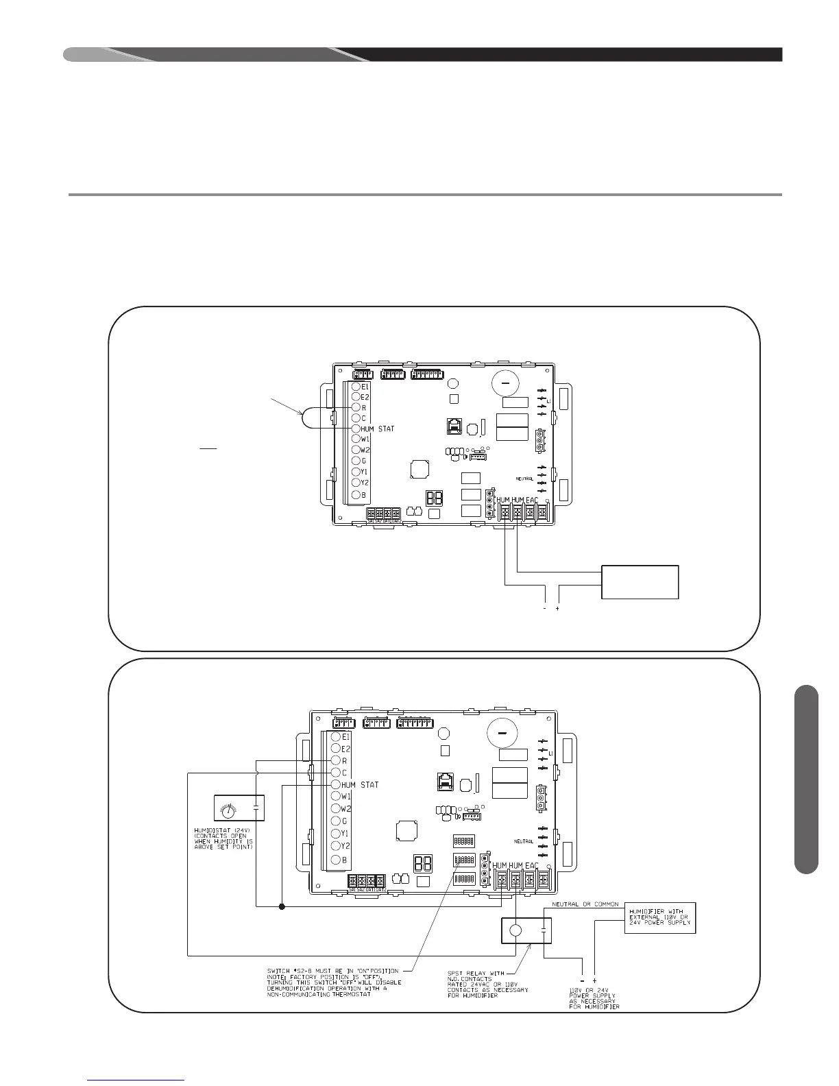
FIGURE 29
WIRING FOR OPTIONAL HUMIDIFICATION (AND DE-HUMIDIFICATION WITH COMMUNICATING THERMOSTAT) WITH OPTIONAL
HUMIDIFIER AND NO HUMIDISTAT (HUMIDIFICATION ACTIVE DURING ANY HEAT CALL)
(FOR USE WITH COMMUNICATING OR NON-COMMUNICATING THERMOSTATS)
ST-A1194-55-01
FIGURE 30
WIRING FOR OPTIONAL DE-HUMIDIFICATION AND HUMIDIFICATION (WITH OPTIONAL HUMIDISTAT AND HUMIDIFIER).
NOTE: CAN BE USED WITH COMMUNICATING OR NON-COMMUNICATING SYSTEMS.
ST-A1194-56-00
 Loading...