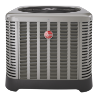
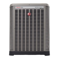
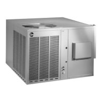
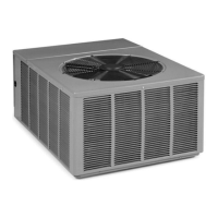
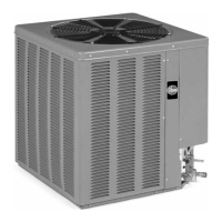
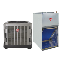
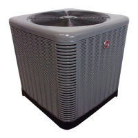
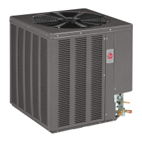
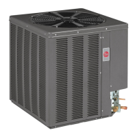
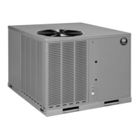
EasyManua.ls Logo

Rheem A13 Series User Manual

Rheem A13 Series
48 pages
To Next Page IconTo Next Page
Page #1 background imageLoading...
Page #1 background image
AIR COOLED
CONDENSING UNITS
92-104921-09-07 (5/16)
Printed in USA
[ ] indicates metric conversions.
Do not destroy this manual.
Please read carefully
and keep in a safe place
for future reference by a
serviceman.
WARNING
THESE INSTRUCTIONS
ARE INTENDED AS AN AID
TO QUALIFIED, LICENSED
SERVICE PERSONNEL FOR
PROPER INSTALLATION,
ADJUSTMENT, AND
OPERATION OF THIS
UNIT. READ THESE
INSTRUCTIONS
THOROUGHLY
BEFORE ATTEMPTING
INSTALLATION OR
OPERATION. FAILURE
TO FOLLOW THESE
INSTRUCTIONS MAY
RESULT IN IMPROPER
INSTALLATION,
ADJUSTMENT, SERVICE,
OR MAINTENANCE
POSSIBLY RESULTING IN
FIRE, ELECTRICAL SHOCK,
PROPERTY DAMAGE,
PERSONAL INJURY, OR
DEATH.
INSTALLATION INSTRUCTIONS
(-)A13, (-)A14 & (-)A16 MODEL SERIES –
13, 14 & 16 SEER
WARNING:
RECOGNIZE THIS SYMBOL
AS AN INDICATION OF
IMPORTANT SAFETY
INFORMATION
ST-A1226-01-00
FEATURING INDUSTRY STANDARD
R-410A REFRIGERANT
earth friendly refrigerant
e
ar
t
h
r
y r
dly
dl
e
n
i
fr
h
NOTE: Actual unit appearance
may vary.

Table of Contents

Questions and Answers:

Rheem A13 Series Specifications

General IconGeneral
SeriesA13 Series
TypeAir Conditioner
SEERUp to 13
Operating Voltage208/230V
Operating Frequency60Hz
RefrigerantR-410A

Summary

IMPORTANT SAFETY INFORMATION

Efficiency Testing Notice

Information regarding procedures for verifying or testing energy efficiency ratings.

GENERAL INFORMATION

Checking Product Received

Instructions for inspecting the unit upon delivery for damage and correctness.

Application

Steps for selecting the right air conditioning equipment based on property survey and heat gain calculation.

ELECTRICAL AND PHYSICAL DATA

Unit Model Number Explanation

Details the coding system used for identifying unit models.

SPECIFICATIONS

Proper Installation

Critical steps for optimal performance, including matching components and following instructions.

INSTALLATION

Choosing a Location

Guidelines for selecting an optimal location for the outdoor unit for longevity and service.

Operational Issues

Considerations for unit placement affecting performance and proximity to other equipment.

Corrosive Environment

How corrosive elements can affect the unit and precautions to take.

For Units With Space Limitations

Clearance recommendations for installing units in confined spaces.

Unit Mounting

Instructions for securely mounting the unit to prevent tipping and ensure stability.

TOOLS AND REFRIGERANT

Tools Required for Installing and Servicing R-410A Models

List of essential tools and equipment needed for R-410A system installation and service.

Specifications of R-410A

Technical properties and compatibility information for R-410A refrigerant.

Quick-Reference Guide For R-410A

Key information and precautions for working with R-410A refrigerant.

REPLACEMENT UNITS

Indoor Coil

Guidance on selecting and installing compatible indoor coils for R-410A systems.

INTERCONNECTING TUBING

Refrigerant Level Adjustment

Procedures for adjusting refrigerant charge based on line set length and configuration.

Liquid Line Selection

Guidelines for selecting the correct liquid line size to ensure proper refrigerant flow and prevent flashing.

Long Line Set Applications

Special considerations for systems with extended refrigerant line sets.

Oil Level Adjustments for Long Line Set Applications

Calculations for adding oil to the system for long line set applications.

Suction Line Selection

Importance of proper suction line sizing for oil return, system capacity, and performance.

Refrigerant Migration During Off Cycle

Managing refrigerant migration to prevent compressor damage and noise during startup.

Tubing Installation

Guidelines for installing refrigerant tubing, including material, sealing, and insulation.

Tubing Connections

Procedures for making secure and proper refrigerant line connections using appropriate brazing alloys.

Leak Testing

Method for performing leak tests on the refrigerant system using dry nitrogen and checking for leaks.

WIRING

Control Wiring

Instructions for low-voltage wiring between the thermostat, indoor unit, and outdoor unit.

Typical Noncommunicating Thermostat Wiring Diagrams

Illustrations of common wiring configurations for noncommunicating thermostats.

Power Wiring

Guidelines for connecting the unit to the power supply, including voltage requirements and conduit.

Grounding

Critical safety procedure for permanently grounding the unit to prevent electrical shock.

START-UP

Checking Airflow

Procedure for verifying adequate airflow through the indoor unit and duct system for optimal performance.

Evacuation Procedure

Steps for removing air and moisture from the system to ensure equipment longevity and efficiency.

Final Leak Testing

Method for detecting leaks in the system after evacuation and repair.

Checking Refrigerant Charge

Procedure for verifying and adjusting the system's refrigerant charge for optimal performance.

Confirm ID Airflow and Coils Are Clean

Ensuring clean indoor airflow and coils are prerequisites for accurate system charging.

Measurement Device Setup

Instructions for connecting pressure gauges and temperature probes for charging.

Charging by Weight

Method for calculating and adding refrigerant based on line set length and unit specifications.

Gross Charging by Pressures

Procedure for making an initial refrigerant charge based on system pressures and outdoor conditions.

Final Charge by Subcooling

Method for fine-tuning the refrigerant charge using subcooling measurements.

Finishing Up Installation

Final steps after charging, including reconnecting covers and setting the thermostat.

COMPONENTS AND CONTROLS

Compressor Crankcase Heat (CCH)

Information on the purpose and installation of crankcase heaters to prevent refrigerant migration.

High- and Low-Pressure Controls (HPC and LPC)

Explanation of high and low-pressure controls used for compressor protection.

ACCESSORIES

Single Pole Compressor Contactor (CC)

Details on single-pole contactors used in single-phase units for compressor operation.

Time Delay Control

Function of the time delay control to prevent compressor damage from power interruptions.

Low Ambient Control (LAC)

Purpose of the low ambient control for maintaining system balance at low outdoor temperatures.

Hard Start Components

Information on hard start components for reducing light dimming during compressor startup.

DIAGNOSTICS

Electrical Checks Flowchart

A step-by-step guide for diagnosing electrical issues within the unit.

Cooling Mechanical Checks Flowchart

A flowchart for diagnosing mechanical problems affecting the unit's cooling operation.

General Troubleshooting Chart

A comprehensive chart listing symptoms, possible causes, and remedies for common unit issues.

Service Analyzer Charts - Compressor Overheating

Analysis of symptoms and causes related to compressor overheating.

Service Analyzer Charts - Electrical

Troubleshooting electrical issues like voltage problems and component failures.

Service Analyzer Charts - Flooded Starts

Diagnosing issues related to liquid refrigerant entering the compressor during startup.

Service Analyzer Charts - Contamination

Identifying and resolving issues caused by moisture, noncondensibles, or debris in the system.

Service Analyzer Charts - Loss of Lubrication

Troubleshooting problems related to insufficient oil return or lubrication in the compressor.

Service Analyzer Charts - Slugging

Diagnosing symptoms of liquid refrigerant slugging the compressor, often caused by improper piping.

Service Analyzer Charts - Flooding

Identifying causes and remedies for refrigerant flooding in the compressor.

Service Analyzer Charts - Thermostatic Expansion Valves

Troubleshooting issues related to the thermostatic expansion valve (TEV) operation.

Related product manuals