17
F
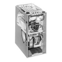
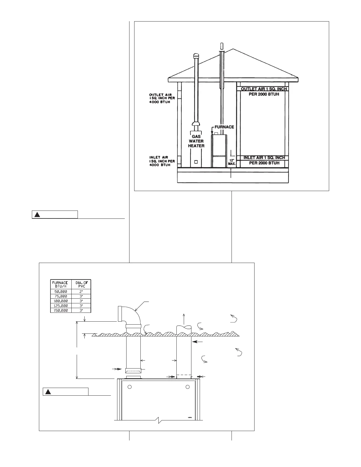
IGURE 10
O
UTSIDE AIR USING A HORIZONTAL INLET & OUTLET
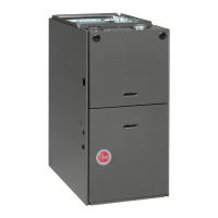
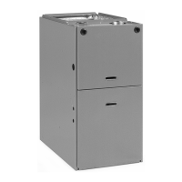
FIGURE 11
COMBUSTION AIR FITTING – OPTIONAL ATTIC COMBUSTION AIR PULL, UPFLOW/HORIZONTAL MODELS ONLY
B: Method 3, Upflow/Horizontal models
B: only
For the optimum in quiet operation,
attic air may be brought directly to the
furnace.
IMPORTANT: In applications using
Method 3 for combustion air, the attic
must be ventilated by gable or soffit
vents. See Figure 8.
COMBUSTION AIR INTAKES
CANNOT BE TERMINATED
OUTSIDE. DOING SO CAN CAUSE
IMPROPER OPERATION OF THE
FURNACE.
If attic combustion air is used, the inlet
air opening at the furnace must be
protected from accidental blockage.
Install a 90° elbow pointing horizontally
at the top of inlet air pipe. See Figure
11 (maximum of 2, 45° or 90° elbows,
allowed).
INCLUDING
HORIZONTAL DIRECTION
ATTACH A 90° ELBOW TO TOP INLET AIR
OPENING TO PREVENT ACCIDENTAL BLOCKAGE
OF INTAKE OPENING.
NOTE: Maximum length of pipe that
may be used for combustion air is 10
feet with two elbows. Lengths of more
than 10 feet can result in nuisance
pressure switch trips.
CAUTION
!
PVC
ELBOW
#8 SCREWS
#8 SCREW
METAL FLUE PIPE ONLY
10 FT. MAX.
12" MIN. FROM
TOP OF INSULATION
6" MINIMUM
CLEARANCE
PVC
COUPLER
EXHAUST
ATTIC SPACE
INDOOR SPACE
INSULATION
CAUTION
!
USE OF SHEET METAL
AIR INTAKE PIPE
INSTEAD OF PVC MAY
RESULT IN NOISE ISSUES.
 Loading...