Do you have a question about the RHINO GX and is the answer not in the manual?
Procedure for activating and deactivating the alarm system via the remote.
Details on what happens when the alarm is triggered and its auto-rearm function.
Activation and cancellation procedure for the emergency panic feature.
Explanation of the two-stage impact sensing system for initial warning.
Automatic arming 30 seconds after leaving the vehicle with ignition off.
System re-arms automatically if not disarmed within 60 seconds.
Disables siren beeps for arm/disarm confirmation; only blinkers flash.
Configures lock/unlock outputs for 0.8 or 5 second pulses for central locking.
Adjusts the sensitivity level of the impact sensing system.
Sets or resets the code for the Security Override Mode.
Disables alarm functions but allows central locking control via remote.
Procedure to add or erase up to three remote controls for the alarm system.
Core functionalities and components of the Rhino GX alarm system.
Features that can be turned on or off to customize system behavior.
Detailed guide for connecting the alarm system wires to the vehicle.
Visual representation of the alarm system's electrical connections.
Instructions for configuring the engine immobilisation circuit.
Recommended positioning for mounting the main alarm unit for optimal performance.
Procedure to disarm the alarm if a remote control is lost or fails.
Diagrams for connecting the alarm to a specific central locking kit.
Wiring for adding central locking motors, e.g., keyless entry on driver's door.
Connection for low current original central locking systems using negative trigger.
Wiring for central locking systems that use positive pulse signals.
Wiring for positive or negative at rest central locking systems.
Wiring configuration for floating switches in central locking.
Wiring diagram for vehicles with negative switching door circuits.
Wiring instructions for vehicles with positive switching door circuits.
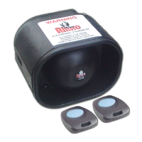
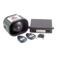
The Rhino GX is a remote control compact car alarm system designed to enhance vehicle security with a range of features, including a 2-stage impact sensor, central locking, and immobilisation outputs. This system is microprocessor-controlled and comes with a multi-function remote control.
The primary function of the Rhino GX is to provide comprehensive security for a vehicle. When armed, it monitors for various triggers and activates an audible siren and visual alerts (blinkers) if a security breach is detected. The system also offers central locking control and engine immobilisation capabilities to prevent unauthorised vehicle operation.
Arming and Disarming: To arm the alarm, a single press of the remote control button is sufficient. The blinkers will flash once, the siren will beep once, and the dash LED will illuminate for 10 seconds before flashing, indicating the alarm is active. Disarming requires another press of the remote button, resulting in two blinker flashes and two siren beeps. If the siren is sounding, the first press will silence it and rearm the system, while a second press is needed to fully disarm. The system retains its armed or disarmed state even if power is temporarily disconnected, such as during a battery replacement.
Alarm Trigger and Memory: Upon triggering, the siren will sound for 30 seconds and then automatically rearm. If the alarm has been triggered in the owner's absence, the dash LED will flash twice as fast as normal, serving as a visual alert upon return to the vehicle.
Emergency Panic Button: The panic feature can be activated by pressing and holding the remote control button for 3 seconds. This will arm or disarm the system depending on its current state, activate the siren, and flash the blinkers for 30 seconds. To cancel panic, the standard disarm procedure is followed. Note that, by Australian law, the panic function is disabled when the ignition is on.
Pre-Alert (2 Stage) Impact Warning: A key security feature is the 2-stage impact sensor. A low-level impact, like a tire kick, will trigger the siren to beep 5 times as a warning. If further impact is detected, the system escalates to full siren mode. The sensitivity of this sensor is adjustable via the remote control, allowing owners to customise it to their needs.
Central Locking Control: The Rhino GX provides negative pulse central locking outputs, allowing integration with the vehicle's existing central locking system. The output pulse time can be selected between 0.8 or 5 seconds, accommodating different vehicle types, including those with vacuum central locking or central closure wires (e.g., some BMW, Mercedes) that automatically close windows and sunroofs.
Engine Immobilisation: The system includes a "Negative on Arm" wire that enables an effective engine immobilisation circuit when configured with an optional 40amp Changeover Relay. This prevents the vehicle from starting when the alarm is armed, typically by interrupting the starter motor circuit.
LED Indicator: A red flashing LED light provides visual status updates for the alarm, indicating arming, disarming, and trigger memory.
Learning Remotes: The Rhino GX supports up to 3 remote controls. To program new remotes or re-program existing ones, all remotes must be present. The process involves disarming the system, opening and closing the driver's door, then cycling the ignition key from off to on 20 times within 30 seconds. The parking lights will flash 3 times to confirm entry into learning mode. Then, each remote button is pressed sequentially, with the siren chirping briefly to confirm each successful learning. The system exits learning mode after receiving 3 remote codes or if the owner repeatedly presses a learned remote to fill all coding locations.
Programmable Features: The Rhino GX offers several programmable features that can be turned on or off to suit individual preferences. These settings are permanently stored in memory, even if power is removed. The programming procedure involves arming and disarming the alarm, turning the ignition to on within 20 seconds, and then pressing the remote control button a specific number of times corresponding to the desired feature's code. After the last press, the ignition is turned off, and the system confirms the new setting with visual flashes (one flash for on, two for off).
Security Override Mode: In case of a lost or malfunctioning remote, the alarm can be disarmed using a manual override procedure. This involves opening and closing the driver's door (which will trigger the siren), then turning the ignition key from off to on a specific number of times within 30 seconds (equal to the chosen security reset code, with 5 being the standard). The siren will stop, and the parking lights will flash for 3 minutes, allowing the vehicle to be started once. This procedure must be repeated for subsequent starts.
The Rhino GX is designed for ease of installation, with clear wiring instructions provided for various connections, including power, earth, parking lights, ignition, negative trigger inputs (for doors, bonnet, boot, and optional sensors), LED output, and central locking. The main unit's mounting position is recommended to be vertical and as close to the centre of the firewall as possible, at least 25cm away from high tension leads, to optimise shock sensor sensitivity and prevent interference. It is crucial that no part of the vehicle touches the unit to avoid affecting sensitivity.
| Alarm Type | 2-Way |
|---|---|
| Ignition Kill | Yes |
| Starter Kill | Yes |
| Door Trigger | Yes |
| Hood Trigger | Yes |
| Trunk Trigger | Yes |
| Remote Start | Yes |
| Keyless Entry | Yes |
| Panic Mode | Yes |
| Valet Mode | Yes |
| Remote Control | Yes |
| Shock Sensor | Yes |
| Battery Backup | Yes |